1. Introduzione
This manual provides essential information for the proper installation, operation, and maintenance of the ICM Controls ICM271C Control Board. The ICM271C is a genuine replacement part designed for specific appliance systems. Please read this manual thoroughly before attempting any installation or service to ensure safety and optimal performance.
2. Informazioni sulla sicurezza
WARNING: Installation and servicing of this control board should only be performed by a qualified technician. Failure to follow these instructions could result in property damage, personal injury, or death.
- Always disconnect power to the appliance before installing, servicing, or removing the control board.
- Assicurarsi che tutti i collegamenti elettrici siano conformi alle normative elettriche locali e nazionali.
- Verifica corretto voltage and current ratings before connecting the board.
- Non bypassare alcun dispositivo di sicurezza.
3. Prodotto finitoview
The ICM Controls ICM271C is a replacement control board designed to manage various functions within an appliance system. It integrates critical components for system operation, including relays, resistors, and connection terminals. This board is engineered to meet the specifications of the original equipment, ensuring compatibility and reliable performance.
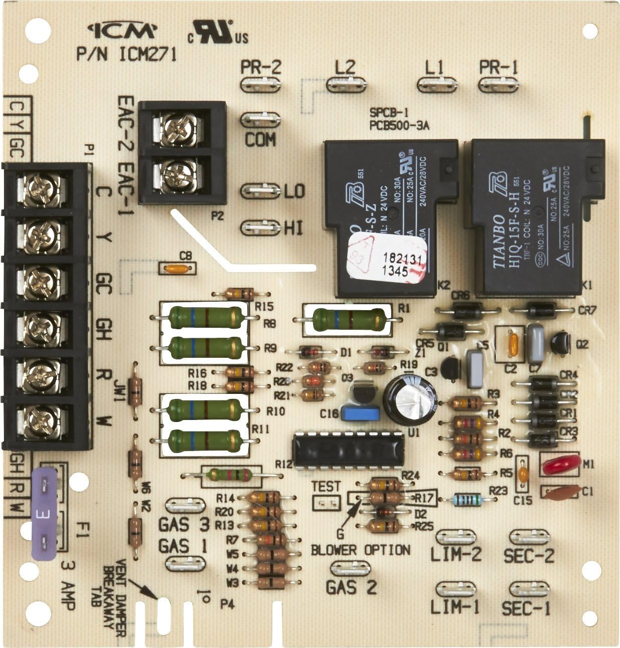
Figura 1: ICM Controls ICM271C Control Board. This image displays the full circuit board with various components including relays, resistors, and terminal blocks for wiring connections. Key labels such as P/N ICM271, EAC-1, EAC-2, COM, LO, HI, GAS 1, GAS 2, GAS 3, LIM-1, LIM-2, SEC-1, SEC-2, and a 3 AMP fuse are visible, indicating its function as a central control unit for an appliance system.
4. Installazione
Before beginning installation, ensure the appliance is completely powered off at the main breaker or disconnect switch. It is highly recommended to photograph the existing wiring configuration before disconnecting any wires from the old control board.
4.1 Passaggi di pre-installazione
- Disconnessione dell'alimentazione: Turn off all power to the appliance at the main service panel. Verify power is off using a voltagetester.
- Documentazione: Take clear photographs of the existing control board and all wire connections. Label each wire as it is removed from the old board.
- Rimozione della vecchia scheda: Scollegare con cautela tutti i cavi e l'hardware di montaggio dalla vecchia scheda di controllo.
4.2 Procedura di installazione
- Montaggio: Secure the new ICM271C control board in the same location as the old board using appropriate mounting hardware.
- Collegamenti elettrici: Refer to your labeled wires and photographs. Connect each wire to the corresponding terminal on the ICM271C board. Ensure all connections are secure and tight. Pay close attention to terminal labels such as EAC-1, EAC-2, COM, LO, HI, GAS 1, GAS 2, GAS 3, LIM-1, LIM-2, SEC-1, SEC-2, and the 3 AMP fusibile.
- Configurazione del ponticello: Some installations may require specific jumper configurations. If your previous board had jumpers, ensure the new board is configured identically or according to the appliance manufacturer's specifications. Note that some older boards may have different terminal spacing for certain connections (e.g., Gas1 and Gas3), potentially requiring a new jumper wire if the original is not compatible.
- Ispezione finale: Double-check all wiring for correctness and security. Ensure no loose wires or tools are left inside the appliance.
4.3 Post-installazione
Once installation is complete and verified, restore power to the appliance. Monitor the system for proper operation. Refer to the appliance's specific user manual for initial startup procedures.
5. Funzionamento
The ICM271C Control Board functions as the central processing unit for your appliance, interpreting signals from thermostats and other sensors to control various components such as blowers, igniters, and gas valves. Once correctly installed, the board operates automatically in conjunction with the appliance's overall system. There are no direct user-operable controls on the board itself.
6. Manutenzione
The ICM271C Control Board is designed for reliable, long-term operation with minimal maintenance. However, periodic inspection by a qualified technician is recommended as part of routine appliance servicing.
- Ispezione visiva: During routine appliance maintenance, visually inspect the control board for any signs of overheating, corrosion, or loose connections.
- Pulizia: Ensure the area around the control board is free from dust, debris, and moisture, which can interfere with its operation.
- Controllo fusibile: La scheda include un 3 AMP fuse (F1). If the appliance experiences a sudden power surge or electrical fault, this fuse may blow to protect the board and other components. If the fuse is blown, replace it with a fuse of the exact same rating (3 AMP). Always disconnect power before checking or replacing the fuse.
7. Risoluzione Dei Problemi
If your appliance is not functioning correctly after installing the ICM271C Control Board, consider the following troubleshooting steps. Always disconnect power before inspecting the board or connections.
- Nessun potere: Verify that power is supplied to the appliance and that the main breaker is on. Check the 3 AMP fuse on the control board (F1).
- Cablaggio errato: Double-check all wire connections against your photographs and the appliance's wiring diagram. Ensure all terminals are securely connected.
- Il sistema non risponde: Confirm that the thermostat is correctly set and calling for heat or cool. Check for any error codes displayed by the appliance (refer to the appliance's manual).
- Problemi dei tifosi: If the fan is not operating correctly, verify the LO and HI fan speed connections.
- Gas Valve Issues: Ensure connections to GAS 1, GAS 2, and GAS 3 terminals are correct.
If troubleshooting does not resolve the issue, it is recommended to contact a qualified HVAC technician for further diagnosis and repair.
8. Specifiche
| Caratteristica | Dettaglio |
|---|---|
| Marca | Controlli ICM |
| Numero di modello | ICM271C |
| Numero di parte | ICM271C |
| Peso dell'articolo | 4 once |
| Dimensioni del prodotto | 5.25 x 5 x 1 pollici |
| Batterie richieste | NO |
| Batterie incluse | NO |
| Valutazione dei fusibili | 3 AMP (F1) |
9. Garanzia e supporto
For warranty information regarding your ICM Controls ICM271C Control Board, please refer to the documentation provided with your purchase or contact ICM Controls directly through their official website. Support for installation and troubleshooting should primarily be sought from a qualified HVAC technician. For general inquiries, you may visit the ICM Controls Store on Amazon.