
1. Introduzione
This manual provides comprehensive instructions for the installation, operation, and maintenance of the Chieftec CI-01B-OP mATX Chasis. This chassis is designed for micro-ATX systems, offering a compact yet versatile solution for PC builders. Please read this manual thoroughly before beginning any installation.

This image displays the Chieftec CI-01B-OP mATX Chasis from a front-side angle, highlighting its black finish and honeycomb mesh front panel design.
2. Contenuto della confezione
Please verify that all items listed below are present in your package before proceeding with installation. If any items are missing or damaged, contact your retailer.
- Chieftec CI-01B-OP mATX Chasis
- Set di viti di montaggio
- Filtro antipolvere
- HDD rails
- Istruzioni di montaggio (questo manuale)
3. Caratteristiche principali
The Chieftec CI-01B-OP mATX Chasis offers several features designed for ease of use and performance:
- Fattore di forma: Compact mATX cube design.
- Pannello frontale: Honeycomb stamped mesh for optimized airflow.
- Porte I/O frontali: 2x USB 3.0, 1x USB 2.0, Mic-in, Audio-out (AZALIA / HD-Audio).
- Baie di guida: 1x 5.25" external, 2x 3.5" internal, 3x 2.5" internal.
- Supporto scheda VGA: Lunghezza massima di 320 mm.
- Supporto per dissipatori CPU: Altezza massima 150 mm.
- Materiale: Durable 0.6mm thick metal construction.

This image shows a close-up of the top panel of the chassis, detailing the integrated USB 3.0, USB 2.0, microphone, and audio ports.
4. Configurazione e installazione
Follow these steps for proper component installation. Ensure the system is powered off and unplugged from the wall outlet before beginning any installation to prevent electric shock or damage to components.
4.1. Preparing the Chasis
Remove the side panels and any necessary covers to access the interior. Refer to the chassis diagram for panel removal instructions.
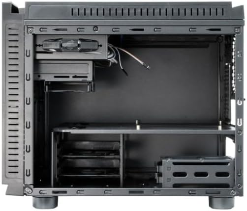
Questa immagine fornisce un interno view of the chassis, showing the motherboard tray, drive bays, and general component layout.
4.2. Installazione della scheda madre
- Installare la schermatura I/O nell'apertura posteriore del telaio.
- Align your micro-ATX motherboard with the pre-installed standoffs inside the chassis.
- Fissare la scheda madre utilizzando le viti fornite. Non serrare eccessivamente.
4.3. Installazione dell'unità di alimentazione (PSU)
- Mount the PSU in its designated area, typically at the rear bottom of the chassis.
- Fissare l'alimentatore con le viti dalla parte posteriore del telaio.
4.4. Installazione dell'unità
- HDD da 3.5": Attach the provided HDD rails to your 3.5" hard drives and slide them into the internal 3.5" drive bays until they click into place.
- 2.5" SSDs/HDDs: Secure 2.5" solid-state drives or hard drives into the dedicated 2.5" bays using screws.
- 5.25" ODD: Install 5.25" optical drives into the external bay from the front and secure them with screws or tool-less mechanisms if available.
4.5. Installazione della scheda grafica (VGA)
- Rimuovere le coperture degli slot di espansione necessari nella parte posteriore dello chassis.
- Insert the graphics card into the appropriate PCIe slot on the motherboard.
- Secure the graphics card with a screw or latch. Ensure the card's length does not exceed 320mm.
4.6. Installazione del dissipatore della CPU
Install your CPU cooler according to its manufacturer's instructions. Ensure the cooler's height does not exceed 150mm to allow the side panel to close properly.
4.7. Gestione dei cavi
Route power and data cables neatly behind the motherboard tray or through designated cutouts. This improves airflow and maintains a clean interior aesthetic.

This image shows the chassis with its top and side panels opened, revealing the internal structure and providing a clear view of the space available for component installation and cable routing.
4.8. Collegamento dei cavi del pannello frontale
Connect the front panel USB 3.0, USB 2.0, audio, power switch, reset switch, and LED cables to the corresponding headers on your motherboard. Refer to your motherboard manual for specific header locations and pin assignments.
5. Funzionamento
Once all components are securely installed and connected, carefully close and secure the chassis panels. Connect the power cable to the PSU and an electrical outlet. Press the power button on the front panel to start your system.
6. Manutenzione
Regular maintenance helps ensure optimal performance and longevity of your chassis and its components.
- Filtri antipolvere: Periodically clean the dust filters (e.g., front mesh, bottom PSU filter) to maintain good airflow and prevent dust buildup inside the system. Dust can impede cooling efficiency.
- Pulizia interna: Use compressed air to remove dust from internal components and fans. Ensure the system is powered off and unplugged before cleaning. Avoid using liquid cleaners inside the chassis.
- Pulizia esterna: Pulire le superfici esterne con un panno morbido e leggermenteamp stoffa. Evitare l'uso di prodotti chimici aggressivi o materiali abrasivi che potrebbero danneggiare la finitura.
7. Risoluzione Dei Problemi
Questa sezione affronta i problemi più comuni che potresti riscontrare durante o dopo l'installazione.
- Il sistema non si accende:
Check all power connections, including the PSU to the wall outlet, the 24-pin ATX power cable and 8-pin CPU power cable from the PSU to the motherboard, and the front panel power switch cable to the motherboard header. Ensure the PSU switch is in the 'ON' position.
- Nessuna uscita di visualizzazione:
Ensure the graphics card is properly seated in its PCIe slot and connected to auxiliary power (if required). Verify the monitor cable is securely connected to the graphics card and the monitor is powered on and set to the correct input.
- I ventilatori non girano:
Check all fan connections to the motherboard or any fan controller. Ensure power cables are properly connected to the fans.
- Front USB ports not working:
Verify that the front panel USB cables (USB 3.0 and USB 2.0) are correctly connected to the corresponding USB headers on your motherboard.
8. Specifiche tecniche
| Caratteristica | Specificazione |
|---|---|
| Nome del modello | CI-01B-OP |
| Fattore di forma | mATX Cube |
| Dimensioni (LxWxH) | 15.75 x 18.11 x 12.99 pollici (400 x 460 x 330 mm) |
| Peso dell'articolo | 11.22 libbre (5.1 kg) |
| Materiale | Metal (0.6mm thick) |
| Colore | Nero |
| External Drive Bays | 1x 5.25" |
| Alloggiamenti per unità interne | 2x 3.5", 3x 2.5" |
| Porte I / O anteriori | 2x USB 3.0, 1x USB 2.0, Mic-in, Audio-out |
| Compatibilità della scheda madre | Micro-ATX |
| Lunghezza massima della scheda VGA | 320mm |
| Altezza massima del dissipatore della CPU | 150mm |
| Montaggio dell'alimentatore | Montaggio posteriore |
| Metodo di raffreddamento | Aria |
9. Garanzia e supporto
For detailed warranty information, technical support, or service inquiries, please refer to the official Chieftec webo contattare il rivenditore locale presso il quale è stato acquistato il prodotto. Conservare la prova d'acquisto per eventuali reclami in garanzia.
Official Chieftec Websito: https://www.chieftec.eu