Walfront Walfrontafg3g8tdsy-03
Walfront DC 5V 12V 24V Adjustable Cycle Trigger Delay Timing Timer Relay On/Off Switch User Manual
Model: Walfrontafg3g8tdsy-03
Prodotto finitoview
The Walfront DC 5V 12V 24V Adjustable Cycle Trigger Delay Timing Timer Relay On/Off Switch is a versatile module designed for precise timing control in various applications. It features adjustable "on" and "off" times and supports both mon (single) and cycle modes. This module is ideal for timer-operated equipment, repetitive test circuits, and intermittent pump control in systems like fish tanks.

Figure 1: Walfront DC Timer Relay Module. This image shows the top view of the green circuit board with a blue relay, two potentiometers for time adjustment, and terminal blocks for connections.
Specifiche
| Specificazione | Valore |
|---|---|
| Ingresso volumetage Opzioni | DC 5V, DC 12V, DC 24V (model dependent) |
| Corrente di riposo | <10mA |
| Corrente dinamica | 45mA@12V; 90mA@5V; 30mA@24V |
| Tipo di contatto | 1 group NO+NC (Normally Open + Normally Closed) |
| Capacità di carico | 10A (AC0-250V, DC0-30V) |
| Dimensioni del modulo | 70mm x 20mm x 18mm (2.75 "x 0.78" x 0.7 ") |
| Precisione del tempo | Max value * 0.001 |
| Adjustable Time Ranges |
|
| Tipo di connettore | Cablato |
| Materiale di contatto | Lega d'argento |
| Tipo di montaggio | Montaggio in superficie |

Figure 2: Dimensions of the Walfront Timer Relay Module. The image shows the module with measurements indicating a length of 70mm and a width of 20mm.
Installazione e cablaggio
Proper wiring is crucial for the safe and correct operation of the timer relay module. Always ensure the power supply matches the module's voltage rating (5V, 12V, or 24V DC) and observe polarity.
Schema elettrico finitoview
The module supports different wiring configurations depending on whether the load shares the same power supply as the module or uses a separate power supply.

Figure 3: Detailed Wiring Diagram for the Walfront Timer Relay Module. This diagram illustrates connections for the module's power supply, a start-up button, and a load, emphasizing not to reverse power supply polarity.
Punti di connessione
- Potenza in ingresso: Connect your DC power supply to the '+' and '-' terminals. Ensure correct polarity.
- Input chiave: The 'Key' terminals are for an external trigger switch (e.g., a push button). Shorting these two wires will trigger the module. If you need the module to work recurrently after power on, connect these two wires directly.
- Uscita relè: Il relè ha tre terminali:
- NC (normalmente chiuso): Connected to COM when the relay is off.
- COM (Comune): Il terminale comune per l'interruttore del relè.
- NO (normalmente aperto): Connected to COM when the relay is on.
Wiring Reference 1: Shared Power Supply
In this configuration, the module and the load share the same power source. This is suitable for DC loads that operate at the module's input voltage.

Figure 4: Wiring Reference 1. This diagram shows the module and load connected to a single power supply (BT1), with the load connected between the COM and NO terminals of the relay, and a trigger switch (S1 Key) connected to the module's key input.
Wiring Reference 2: Separate Power Supply for Load
This configuration allows the module to control a load that uses a different voltage (AC or DC) than the module's power supply. The relay acts as a switch for the load's independent circuit.
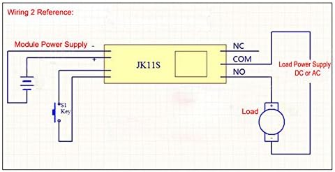
Figure 5: Wiring Reference 2. This diagram illustrates the module powered by one supply, while the load is powered by a separate supply (DC or AC) through the relay's COM and NO terminals. A trigger switch (S1 Key) is also shown.
Istruzioni per l'uso
The module supports two main operating modes: Mon (single trigger) and Cycle. The timing for "on" and "off" states is adjustable using the onboard potentiometers.
Selezione della modalità
The operating mode is selected using a jumper on the module. Locate the jumper labeled "Mon" and "Cyc".
- Mon Mode (Single Trigger): When the jumper is on "Mon", the module operates in single trigger mode. Upon receiving a trigger, the relay will switch on, and after the set delay time, it will switch off. If triggered again during the delay process, the current delay will be interrupted and reset.
- Modalità ciclo: When the jumper is on "Cyc", the module operates in cycle mode. Upon receiving a trigger, the relay will switch on for a set "on" time (T1), then switch off for a set "off" time (T2), and this cycle will repeat indefinitely until interrupted. If triggered again during the delay process, the current delay will be interrupted and reset.

Figure 6: Jumper settings for selecting working mode (Mon/Cycle) and time range (T/T10). The image highlights the two jumpers on the circuit board.
Regolazione del tempo
The module features two adjustable potentiometers for setting the timing intervals. These are typically labeled for "on" time and "off" time, or T1 and T2 in cycle mode.
- Adjust "On" Time (T1): Use the potentiometer labeled "+OnT" or similar to set the duration the relay remains active.
- Adjust "Off" Time (T2): Use the potentiometer labeled "+OffT" or similar to set the duration the relay remains inactive (in cycle mode).
The time range can also be adjusted using a separate jumper, typically labeled "T" and "T/10".
- "T" Position: Normal time range.
- "T/10" Position: Time is divided by 10, allowing for finer adjustment within a smaller range.

Figure 7: Potentiometers for adjusting "on" and "off" times. The image points out the two blue potentiometers and the power and switch indicator LEDs.
Luci di segnalazione
- Indicatore di alimentazione: Illuminates when the module is powered on.
- Indicatore di commutazione: Illuminates when the relay is active (switched on).
Applicazioni
This versatile timer relay module can be used in a variety of applications requiring precise timing and control:
- Timer operating equipment
- Machine repetitive test circuits
- Fish tank intermittent pump control
- Automated lighting systems
- DIY automation projects
- Sistemi di controllo industriale
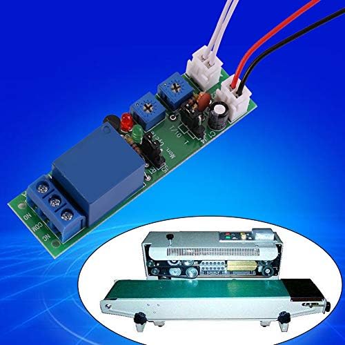
Figura 8: Esample application of the Walfront Timer Relay Module. The image shows the module alongside a conveyor belt sealing machine, illustrating its use in automated processes.
Risoluzione dei problemi
If you encounter issues with your Walfront Timer Relay Module, consider the following troubleshooting steps:
- Il modulo non si accende:
- Verificare il volume immessotage matches the module's rating (5V, 12V, or 24V DC).
- Check power supply connections for correct polarity (+ to +, - to -). Reverse polarity can damage the module.
- Ensure the power supply is providing sufficient current.
- Relay Not Triggering/Switching:
- Confirm the 'Key' input is correctly wired and the trigger signal is being applied (e.g., button press, short circuit).
- In Mon mode, ensure the trigger is a momentary signal if continuous triggering is not desired.
- Check the potentiometer settings; they might be set to a very short or very long duration.
- Verify the mode jumper (Mon/Cyc) is correctly positioned for your desired operation.
- Inconsistent Timing:
- Ensure the power supply is stable and free from significant voltage fluttuazioni.
- Check the "T" / "T/10" jumper setting to ensure the correct time scaling is selected.
- Adjust potentiometers slowly and test to find the desired timing.
- Load Not Operating:
- Verify the load's power supply is connected and functional.
- Check the relay output connections (COM, NO, NC) to ensure the load is wired to the correct terminals for your desired operation.
- Ensure the load's current and voltage requirements do not exceed the relay's load capacity (10A, AC0-250V, DC0-30V).
Manutenzione
The Walfront Timer Relay Module is designed for low maintenance. Follow these guidelines to ensure its longevity:
- Mantenere pulito: Periodically clean the module with a soft, dry cloth to remove dust and debris. Avoid using liquids or harsh chemicals.
- Condizioni ambientali: Operate the module within its specified temperature and humidity ranges. Avoid extreme temperatures, direct sunlight, and high moisture environments.
- Connessioni sicure: Regularly check all wiring connections to ensure they are secure and free from corrosion. Loose connections can lead to intermittent operation or damage.
- Evitare il sovraccarico: Do not exceed the specified load capacity of the relay (10A, AC0-250V, DC0-30V). Overloading can damage the relay and the module.
Garanzia e supporto
For warranty information and technical support, please refer to the Walfront official websul sito o contatta il tuo punto vendita. Conserva la ricevuta d'acquisto come prova d'acquisto.
For further assistance, you may visit the Walfront Store on Amazon: Walfront Store.
Documenti correlati - Walfrontafg3g8tdsy-03
 |
User Manual: 12V/24V/36V 15A PWM DC Motor Speed Controller (GS00574) Operational guide and safety instructions for the GS00574 PWM DC Motor Speed Controller, featuring specifications and usage guidelines. |
 |
Pressure Threshold Switch Circuit Guide - WALFRONT S40 Technical guide for the WALFRONT S40 pressure threshold switch, explaining the Wheatstone bridge and voltage comparator circuit operation. |
 |
Product Manual: WALFRONT Electronic Transformer ESDB332.11 User manual and compliance information for the WALFRONT Electronic Transformer model ESDB332.11, including manufacturer details and usage instructions. |
 |
User Manual: Mini Cordless Rotating Tool Kit (Model 10112402562) User manual for the WALFRONT Mini Cordless Rotating Tool Kit, featuring 5-speed settings, USB charging, and usage instructions for engraving, sanding, and grinding. |
 |
WALFRONT DC Motor Speed Regulator User Manual (10102500106) User manual for the WALFRONT DC Motor Speed Regulator (Model 10102500106), featuring wireless remote control, 6V-28V PWM stepless speed regulation, and 5A capacity. |
 |
User Manual for WALFRONT 7.5KV 30mA Neon Light Electronic Transformer (NP-7500-30) User manual and safety instructions for the WALFRONT 7.5KV 30mA NP-7500-30 Neon Light Electronic Transformer. Includes manufacturer and compliance details. |
Ask a question about this manual
Ask about setup, troubleshooting, compatibility, parts, safety, or missing instructions. Manuals+ will review the question and use this page’s manual context to help answer it.