1. Introduzione
This manual provides detailed instructions for the safe and efficient use of the Walfront 1200W DC-DC Constant Current Boost Converter. This module is designed to step up a DC input voltage to a higher DC output voltage, offering both constant voltage and constant current capabilities. It is suitable for various applications, including driving high-power LEDs, charging batteries, and as a general voltage regolatore.
2. Informazioni sulla sicurezza
WARNING: Improper use of this module can result in electric shock, fire, or damage to the device and connected equipment. Always follow these safety guidelines:
- Prima di applicare l'alimentazione, assicurarsi che tutti i collegamenti siano sicuri e corretti.
- Do not exceed the specified input or output voltage e limiti di corrente.
- Always connect the input power supply with the correct polarity. Reverse input polarity protection is present but should not be relied upon for continuous operation.
- Ensure adequate ventilation and heat dissipation, especially when operating at high power levels. The integrated fan will activate at 55°C.
- Tenere il modulo lontano da umidità, polvere e materiali infiammabili.
- Only qualified personnel should perform installation and adjustments.
- Disconnect power before making any adjustments or connections.
3. Prodotto finitoview
The Walfront 1200W DC-DC Boost Converter is a high-performance power module featuring a robust design with a large heat sink and an integrated cooling fan for efficient thermal management. It provides a wide range of adjustable output voltage and current, making it versatile for various power conversion needs.

Figura 1: Generale view of the Walfront 1200W DC-DC Boost Converter module.
Caratteristiche principali:
- Ingresso volumetage Gamma: da CC 10 V a 60 V
- Volume di uscitatage Range: DC 12V to 83V (continuously adjustable)
- Maximum Input Current: 20A (up to 25A with enhanced cooling at 12V-24V)
- Maximum Output Current: 18A (dependent on voltage difference and heat dissipation)
- Constant Current Range: 0.5A to 18A (adjustable)
- High Conversion Efficiency: 92% to 97%
- Integrated Heat Sink and Cooling Fan for optimal thermal performance.
- Screw terminals for easy and secure wire connections.
- Features include reverse input protection (150A MOS), lower voltage protection (9V to 50V adjustable), input over-current protection (25A), and short circuit protection (30A input).
Dimensioni:

Figura 2: Dimensions of the boost converter module. Length: 130mm, Width: 64mm, Height: 52mm.
The module measures approximately 130mm (length) x 64mm (width) x 52mm (height).
4. Specifiche
| Parametro | Valore |
|---|---|
| Tipo | Non-isolated boost module |
| Ingresso volumetage | DC 10V a 60V |
| Corrente di ingresso | 20A (25A max at 12V-24V with cooling) |
| Corrente di riposo | 15mA (increases with voltage conversione) |
| Volume di uscitatage | 12V to 83V (continuously adjustable, default 19V) |
| Corrente di uscita | 18A (max, depends on voltage difference and heat dissipation) |
| Constant Current Range | 0.5A to 18A (+/-0.3A) |
| Reverse Input Protection | Yes (150A MOS) |
| Volume inferioretage Protezione | Yes (9V to 50V adjustable) |
| Ventola di controllo della temperatura | Yes (starts > 55°C) |
| Temperatura di esercizio | -40°C to 85°C (enhance heat dissipation if high) |
| Frequenza | 150KHz |
| Efficienza di conversione | 92% to 97% (depends on voltage/current difference) |
| Input Over-current Protection | Yes (auto when input > 25A) |
| Protezione da cortocircuito | Yes (30A input) |
| Metodo di cablaggio | Terminals (use large current copper wire) |
| Dimensioni | 130 × 64 × 52mm / 5.12 × 2.52 × 2.04 inches |
| Peso | Circa 10.6 once (0.66 libbre) |
5. Impostazione
Before connecting the module, ensure your power source and load are within the specified operating ranges.
5.1. Collegamenti elettrici
The module features screw terminals for input and output connections. Use appropriate gauge copper wire for high current applications.
- Ingresso: Connect your DC power source to the "VIN+" (positive input) and "VIN-" (negative input) terminals.
- Produzione: Connect your load to the "VOUT+" (positive output) and "VOUT-" (negative output) terminals.

Figura 3: Input (VIN) and Output (VOUT) screw terminals for wiring connections.
Important: Double-check all wiring for correct polarity and secure connections before applying power. Loose connections can cause arcing and damage.
5.2. Initial Adjustment (No Load Recommended)
It is recommended to perform initial voltage adjustments without a load connected to prevent damage to your load if the output voltage is set too high.
- Connect the input power supply (within 10V-60V).
- Utilizzando un multimetro, misurare il volumetage across the VOUT+ and VOUT- terminals.
- Regolare il Voltage Adjustment Potentiometer (labeled "CV" or "V-ADJ") clockwise to increase the output voltage, or counter-clockwise to decrease it, until the desired output voltage is reached. The default output voltage è 19V.
- IL Current Adjustment Potentiometer (labeled "CC" or "I-ADJ") should be set to its minimum (fully counter-clockwise) during initial voltage setup to ensure constant current mode does not interfere.
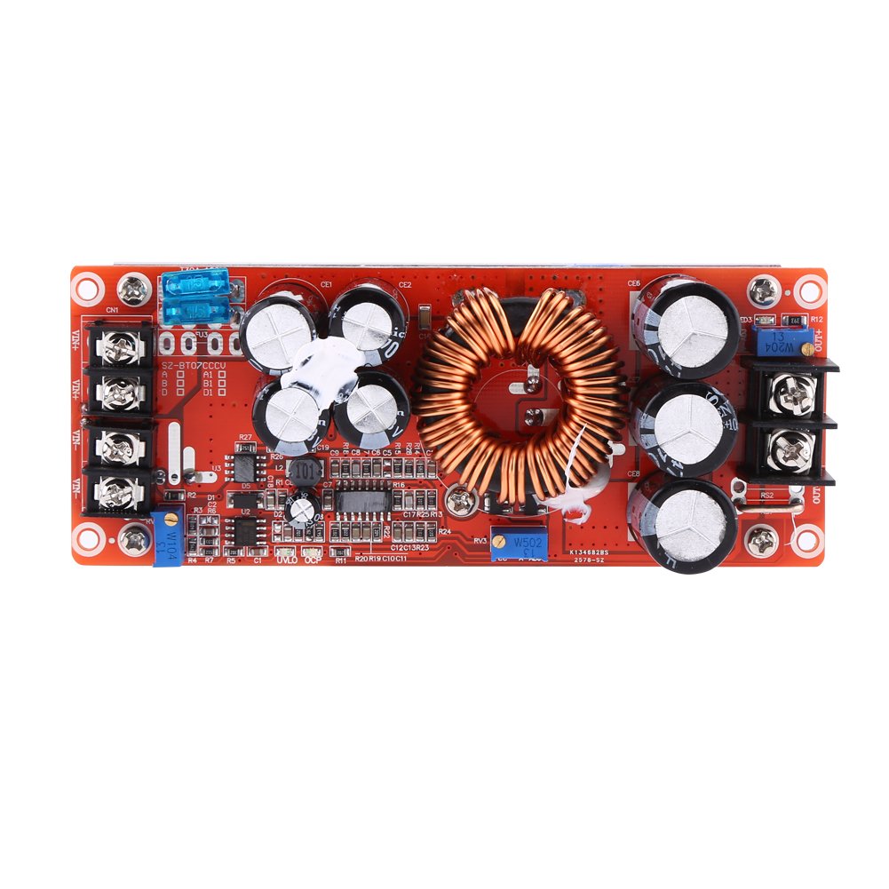
Figura 4: Posizione del Voltage (CV) and Current (CC) adjustment potentiometers.
6. Istruzioni per l'uso
6.1. Volume di uscitatage Regolazione
After initial setup, you can fine-tune the output voltage. Connect your load and monitor the output voltage with a multimeter. Turn the Voltage Adjustment Potentiometer (CV) clockwise to increase voltage or counter-clockwise to decrease it. Ensure the output voltage does not exceed the maximum rating of your load.
6.2. Constant Current (CC) Adjustment
This module can operate in constant current mode, useful for charging batteries or driving LEDs. To set the constant current limit:
- First, set the desired output voltage as described above.
- Connect a suitable load that will draw more current than your desired limit (e.g., a power resistor or a discharged battery).
- Girare il Current Adjustment Potentiometer (CC) clockwise to increase the current limit. Monitor the output current with an ammeter in series with the load.
- Adjust the potentiometer until the desired constant current value is reached. Once the load attempts to draw more current than this set limit, the module will automatically switch to constant current mode, limiting the output current to the set value.
Note: When operating in constant current mode, the output voltage will drop to maintain the set current, depending on the load's resistance.
6.3. Lower Voltage Protection (LVP) Adjustment
The module includes an adjustable lower voltage protection feature to prevent the input source (e.g., a battery) from being over-discharged.
- Connect the input power supply.
- Regola il volume di ingressotage to the desired LVP threshold (e.g., 10V for a 12V battery).
- Girare il Volume inferioretage Protection Potentiometer (labeled "LVP" or "UVLO") counter-clockwise until the output voltage drops to zero or the output indicator LED turns off.
- Slowly turn the potentiometer clockwise until the output voltage reappears. This sets the LVP. When the input voltage drops below this threshold, the module will stop outputting power.
Caution: Incorrect LVP setting can lead to premature shutdown or over-discharge of your input source.
7. Manutenzione
The Walfront 1200W DC-DC Boost Converter is designed for reliable operation with minimal maintenance. However, proper care ensures longevity and performance.
- Dissipazione del calore: The module is equipped with a heat sink and a temperature-controlled fan. Ensure the fan is not obstructed and that there is sufficient airflow around the module, especially when operating at high power. The fan will automatically start when the module temperature exceeds 55°C.
- Pulizia: Periodically inspect the module for dust accumulation on the fan and heat sink. Use compressed air or a soft brush to gently clean these components. Ensure power is disconnected before cleaning.
- Connessioni: Regularly check all wiring connections for tightness and signs of corrosion. Re-tighten if necessary.
- Condizioni ambientali: Operate the module within its specified temperature range (-40°C to 85°C) and avoid environments with high humidity or corrosive gases.

Figura 5: Metter il fondo a view showing the integrated cooling fan for heat dissipation.
8. Risoluzione Dei Problemi
If you encounter issues with your boost converter, refer to the following common problems and solutions:
| Problema | Possibile causa | Soluzione |
|---|---|---|
| Nessun volume di uscitatage. |
|
|
| Volume di uscitatage is unstable or fluctuates. |
|
|
| Module overheats. |
|
|
| Output current is lower than expected. |
|
|
9. Informazioni sulla garanzia
Walfront products are manufactured to high-quality standards. This product is covered by a standard manufacturer's warranty against defects in materials and workmanship. Please retain your proof of purchase for warranty claims. The warranty does not cover damage caused by improper installation, misuse, unauthorized modifications, or operation outside the specified parameters.
10. Supporto
For technical assistance, troubleshooting not covered in this manual, or warranty inquiries, please contact Walfront customer support through your original point of purchase or visit the official Walfront websito per le informazioni di contatto.
Please refer to the Walfront Store on Amazon for additional product information and support resources: Walfront Store