IP-COM G3224P
IP-COM G3224P 24-Port Managed PoE Switch
Manuale d'uso
Model: G3224P | Brand: IP-COM
1. Introduzione
This user manual provides comprehensive instructions for the installation, operation, maintenance, and troubleshooting of the IP-COM G3224P 24-Port Managed PoE Switch. Please read this manual thoroughly before using the device to ensure proper and safe operation.
The IP-COM G3224P is a high-performance managed Power over Ethernet (PoE) switch designed for small to medium-sized businesses and enterprise networks. It offers 24 Gigabit Ethernet ports with PoE+ capabilities and additional SFP ports for fiber uplinks, providing flexible and scalable network solutions.
2. Prodotto finitoview
2.1 Contenuto della confezione
- IP-COM G3224P 24-Port Managed PoE Switch
- Cavo di alimentazione
- Kit di montaggio su rack (staffe e viti)
- Piedini in gomma (per il posizionamento sulla scrivania)
- Guida di installazione rapida
2.2 Descrizione del pannello frontale
The front panel of the IP-COM G3224P switch features various ports and LED indicators for status monitoring.
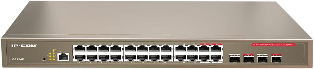
Figure 2.1: IP-COM G3224P Front Panel Layout
This image displays the front panel of the IP-COM G3224P switch. On the left, the IP-COM logo and model number G3224P are visible. To the right, there are LED indicators for SYS, PoE MAX, and individual port status. A console port is also present. The main section features 24 Gigabit Ethernet RJ45 ports, arranged in two rows, with port numbers 1 through 24. On the far right, there are four SFP ports labeled SFP1, SFP2, SFP3, and SFP4, which are used for fiber optic uplinks.
2.3 Indicatori LED
| Indicatore LED | Stato | Descrizione |
|---|---|---|
| SISTEMA | Verde (Fisso) | Il sistema funziona normalmente. |
| SISTEMA | Verde (lampeggiante) | System is booting up or firmware is being upgraded. |
| PoE MASSIMO | Rosso (fisso) | PoE power budget is nearing or exceeding its limit. |
| Collegamento/Azione (per porta) | Verde (Fisso) | La porta è collegata. |
| Collegamento/Azione (per porta) | Verde (lampeggiante) | Port is transmitting or receiving data. |
| PoE (per porta) | Giallo (solido) | L'alimentazione PoE viene fornita al dispositivo connesso. |
3. Configurazione e installazione
3.1 Precauzioni di sicurezza
- Garantire l'alimentazione voltage matches the switch's requirements (240V as per specifications).
- Non ostruire le aperture di ventilazione.
- Tenere il dispositivo lontano da acqua, fuoco e temperature elevate.
- Non tentare di aprire o riparare da soli il dispositivo.
3.2 Installazione su rack
- Fissare le staffe per il montaggio su rack fornite ai lati dello switch utilizzando le viti in dotazione.
- Fissare lo switch in un rack standard da 19 pollici utilizzando le apposite viti per rack (non incluse).
- Ensure adequate airflow around the switch for proper cooling.
3.3 Installazione desktop
- Collegare i piedini in gomma forniti alla parte inferiore dell'interruttore.
- Place the switch on a flat, stable surface with sufficient ventilation.
3.4 Collegamento dello switch
- Collegamento elettrico: Connect the power cord to the power inlet on the rear panel of the switch and then to a grounded power outlet.
- Dispositivi di rete: Connect network devices (e.g., computers, servers, IP cameras, VoIP phones) to the RJ45 ports (1-24) on the front panel using standard Ethernet cables.
- Dispositivi PoE: For PoE-powered devices, simply connect them to any of the RJ45 ports. The switch will automatically detect and provide power if the device is PoE compliant.
- Connessioni in salita: Use the SFP ports (SFP1-SFP4) for fiber optic uplinks to other network devices or the core network. Insert compatible SFP transceivers into the SFP slots before connecting fiber optic cables.
- Connessione alla console (facoltativa): For initial configuration or advanced management, connect a console cable from your computer to the console port on the switch.
4. Istruzioni per l'uso
4.1 Accensione iniziale
After connecting the power cord, the switch will automatically power on. Observe the SYS LED indicator. It will blink during boot-up and turn solid green once the system is ready.
4.2 Connettività di rete di base
Once powered on, the switch will automatically detect connected devices. The Link/Act LED for each connected port will illuminate solid green, indicating a successful link. It will blink when data is being transmitted or received.
4.3 Funzionamento PoE
When a PoE-compatible device is connected to a port, the switch will negotiate power delivery. The PoE LED for that port will turn yellow, indicating that power is being supplied. Monitor the PoE MAX LED; if it turns red, the total PoE power budget is being approached or exceeded, and you may need to reduce the number of PoE devices or use a higher-capacity power source.
4.4 Accesso alla gestione
The IP-COM G3224P is a managed switch, offering various configuration options via a web-based GUI, CLI (Command Line Interface) via the console port, or SNMP. Refer to the detailed management guide (usually available on the manufacturer's website) for advanced configuration, including VLANs, QoS, port mirroring, and security settings.
- Web Interfaccia grafica: Accedi allo switch web interface by typing its default IP address (check the Quick Installation Guide or manufacturer's documentation) into a web browser.
- CLI: Connect via the console port using a terminal emulator (e.g., PuTTY) with appropriate serial port settings.
5. Manutenzione
5.1 Pulizia
- Regularly clean the exterior of the switch with a soft, dry cloth.
- Non utilizzare detergenti liquidi o aerosol.
- Assicurarsi che le aperture di ventilazione siano libere da polvere e ostruzioni.
5.2 Aggiornamenti firmware
Periodically check the IP-COM official webSito per gli aggiornamenti del firmware. Mantenere il firmware aggiornato garantisce prestazioni ottimali, sicurezza e accesso a nuove funzionalità. Seguire attentamente le istruzioni fornite con il pacchetto di aggiornamento del firmware.
5.3 Considerazioni ambientali
Ensure the switch operates within its specified environmental conditions (temperature, humidity) to prevent damage and ensure longevity.
6. Risoluzione Dei Problemi
| Problema | Possibile causa | Soluzione |
|---|---|---|
| No power / SYS LED off | Cavo di alimentazione non collegato o presa di corrente difettosa. | Controllare il collegamento del cavo di alimentazione. Provare una presa di corrente diversa. |
| No link on a port (Link/Act LED off) | Cable issue, device off, or incorrect port. | Check Ethernet cable. Ensure connected device is powered on. Try a different port or cable. |
| PoE device not powering on (PoE LED off) | Device not PoE compliant, cable issue, or power budget exceeded. | Verify device is PoE compliant. Check cable. Check PoE MAX LED; if red, reduce PoE load. |
| Problemi di prestazioni di rete | Cable quality, network congestion, or incorrect configuration. | Use high-quality Ethernet cables. Check for network loops. Review switch configuration (VLANs, QoS). |
| Impossibile accedere web interfaccia di gestione | Incorrect IP address, network settings, or firewall. | Verify the switch's IP address. Ensure your computer is on the same subnet. Disable temporary firewalls. |
If problems persist, consult the full product documentation or contact IP-COM technical support.
7. Specifiche
| Caratteristica | Dettaglio |
|---|---|
| Modello | G3224P |
| Porti | 24 x 10/100/1000Base-T (RJ45) with PoE+, 4 x 1000Base-X (SFP) |
| Capacità di commutazione | 56 Gbps |
| Tasso di inoltro | 41.66 Mpps |
| PoE standard | IEEE 802.3af / at |
| Ingresso volumetage | 240 Volt |
| Dimensioni (L x P x A) | Dimensioni: 29 x 44 x 44 cm |
| Peso | 15 chilogrammi |
| Rackmount | SÌ |
| Gestione | Gestito (Web GUI, CLI, SNMP) |
Nota: le specifiche sono soggette a modifiche senza preavviso.
8. Garanzia e Supporto Tecnico
8.1 Informazioni sulla garanzia
IP-COM products typically come with a limited warranty. Please refer to the warranty card included with your product or visit the official IP-COM websito per termini e condizioni di garanzia dettagliati specifici per la tua regione e la data di acquisto.
8.2 Supporto tecnico
For technical assistance, product inquiries, or troubleshooting beyond the scope of this manual, please contact IP-COM technical support. Support contact information can usually be found on the official IP-COM websito o nella confezione del prodotto.
IP-COM Official Websito: www.ip-com.com.cn
Ask a question about this manual
Ask about setup, troubleshooting, compatibility, parts, safety, or missing instructions. Manuals+ will review the question and use this page’s manual context to help answer it.