
LUX P111
Manuale di istruzioni del termostato non programmabile Lux Pro modello P111
Your guide to simple and efficient home climate control.
Prodotto finitoview
The Lux Pro Model P111 is a non-programmable thermostat designed for straightforward and reliable temperature control in your home. It offers essential features for managing your heating and cooling systems with ease.

Figure 1: Lux Pro P111 Non-Programmable Thermostat. This image displays the front view of the thermostat, showing its LCD screen, fan and system mode switches, and temperature adjustment buttons.
- Installazione semplice: Designed for simple setup with clear instructions.
- Funzionamento non programmabile: Provides direct temperature control without complex scheduling.
- Doppia potenza: Operates on 2 AA alkaline batteries (included) or 24-volt system power.
- Display retroilluminato: Presenta un facileview backlight for clear temperature readings.
- Protezione delle apparecchiature: Includes a selectable 5- or 2-minute time delay to safeguard your HVAC equipment.
- Limiti regolabili: Allows setting of heating and cooling temperature limits.
- Opzioni di visualizzazione della temperatura: Switch between Fahrenheit (℉) or Celsius (℃) display.

Figure 2: Key Features of Lux Pro P111 Thermostat. This graphic highlights features such as Keyboard Lockout, Adjustable Heating and Cooling Limits, Back-Lit Display, Dual Power, and a 5-Year Limited Warranty.
Compatibilità del sistema
The Lux Pro P111 thermostat is designed for compatibility with various HVAC systems. Please review the following compatibility chart to ensure it meets your system requirements.

Figure 3: System Compatibility Chart. This chart details which heating and cooling systems are compatible (e.g., Gas/Oil/Electric Furnace, Heat Pump without Auxiliary Heat, 2-wire Hydronic, 750 Millivolt, Gas Fireplaces, Single Stage Cooling) and which are not (e.g., Heat Pump Multistage, Radiant Ceiling Heat, Electric Baseboards, 3-wire Hydronic, Multistage systems, Portable space heaters, Plug-in air conditioners).
Configurazione e installazione
Una corretta installazione è fondamentale per il funzionamento ottimale del termostato. In caso di dubbi su alcuni passaggi, si consiglia di consultare un tecnico HVAC qualificato.
1. Requisiti di alimentazione
The P111 thermostat can be powered by two (2) AA alkaline batteries or by a 24-volt system. Batteries are included for convenience and reliable operation.
2. Schemi elettrici
Refer to the following diagrams for common wiring configurations. Ensure power to your HVAC system is turned off at the circuit breaker before beginning any wiring.
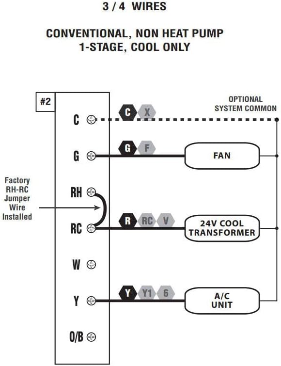
Figure 4: Wiring Diagram for 3/4 Wires. This diagram illustrates the wiring for a conventional, non-heat pump, 1-stage, cool-only system, showing connections for C (optional system common), G (FAN), RH (24V COOL TRANSFORMER), RC (24V COOL TRANSFORMER), and Y (A/C UNIT). A factory RH-RC jumper wire is installed.

Figure 5: Wiring Diagram for 4/5 Wires. This diagram shows the wiring for a conventional, non-heat pump, 1-stage calore e 1-stage cool system, with connections for C (optional system common), G (FAN), RH (24V TRANSFORMER), RC (24V TRANSFORMER), W (HEATER), and Y (A/C UNIT). A factory RH-RC jumper wire is installed.

Figure 6: Wiring Diagram for 5/6 Wires. This diagram illustrates the wiring for a conventional, non-heat pump, 1-heat / 1-cool system with two transformers, showing connections for C (optional system common), G (FAN), RH (24V HEAT TRANSFORMER), RC (24V COOL TRANSFORMER), W (HEATER), and Y (A/C UNIT). The factory RH-RC jumper wire must be removed for this configuration.
3. Montaggio
The thermostat is designed for wall mounting. Use the provided screws and wall anchors for secure installation. Ensure the thermostat is level for accurate temperature readings.
Istruzioni per l'uso
The Lux Pro P111 thermostat features an intuitive control panel for easy operation.

Figure 7: Control Panel Diagram. This diagram labels the key components of the thermostat's front panel: Fan Mode Switch (Fan Auto/On), System Mode Switch (Heat/Off/Cool), LCD Display Screen, SET Button, and UP and DOWN Buttons.
1. Interruttore della modalità di sistema
- CALORE: Attiva il sistema di riscaldamento.
- OFF: Disattiva sia il sistema di riscaldamento che quello di raffreddamento.
- FREDDO: Attiva il sistema di raffreddamento.
2. Interruttore modalità ventola
- AUTO: La ventola funziona solo quando il sistema di riscaldamento o raffreddamento è in funzione.
- SOPRA: La ventola funziona continuamente, indipendentemente dal fatto che sia attivo il sistema di riscaldamento o di raffreddamento.
3. Regolazione della temperatura
Utilizzare il UP (▲) E GIÙ (▼) buttons to set your desired temperature. The current temperature will be displayed prominently on the LCD screen.
4. Attivazione della retroilluminazione
Press any button to activate the backlight for improved visibility in low-light conditions. The backlight will automatically turn off after a short period of inactivity.
5. Temperature Display (Fahrenheit/Celsius)
The thermostat allows you to switch between Fahrenheit (℉) and Celsius (℃) temperature displays. Refer to the full instruction manual for specific steps on how to change this setting, typically found in the advanced settings menu.
6. Equipment Protection Time Delay
The thermostat features a selectable 5- or 2-minute time delay for equipment protection. This delay prevents short cycling of your heating and cooling system, which can extend the lifespan of your equipment. This setting is usually configured during initial setup or in advanced settings.
7. Blocco tastiera
To prevent unauthorized adjustments, the thermostat includes a keypad lockout feature. Consult the detailed manual for instructions on how to activate and deactivate this function.
Manutenzione
1. Sostituzione della batteria
When the battery indicator appears on the display, replace the two (2) AA alkaline batteries. Ensure proper polarity when inserting new batteries. The thermostat retains settings during battery replacement.
2. Pulizia
Pulisci l'esterno del termostato con un panno morbido eamp panno. Non utilizzare detergenti abrasivi o solventi, poiché potrebbero danneggiare la finitura o i componenti interni.
Risoluzione dei problemi
If you encounter issues with your Lux Pro P111 thermostat, consider the following common solutions:
- No Display or Low Battery Indicator: Sostituire le batterie con batterie alcaline AA nuove.
- Il sistema non risponde (riscaldamento/raffreddamento):
- Check that the system mode switch is set to HEAT or COOL.
- Ensure the fan mode switch is set to AUTO or ON.
- Verify that the circuit breaker for your HVAC system is not tripped.
- Confirm that the wiring connections are secure and correct according to the installation diagrams.
- Allow for the equipment protection time delay (5 or 2 minutes) to elapse before the system activates.
- Lettura errata della temperatura: Assicurarsi che il termostato non sia esposto alla luce solare diretta, a correnti d'aria o a fonti di calore che potrebbero interferire con il funzionamento del sensore.
- Tastiera non reattiva: Check if the keypad lockout feature is active. Refer to the manual for deactivation steps.
For persistent issues, refer to the complete user manual or contact customer support.
Specifiche
| Caratteristica | Dettaglio |
|---|---|
| Marca | LUSSO |
| Nome del modello | P111 |
| Dimensioni del prodotto | 4"P x 7"L x 7"A |
| Tipo di controllore | Premere il pulsante |
| Caratteristiche speciali | Lighted Display, Temperature Display |
| Colore | P111-white |
| Usi specifici | Condizionatore d'aria, pompa di calore |
| Tipo di controllo della temperatura | Manuale |
| Componenti inclusi | Pro P111 Non-Programmable Thermostat; 1 Heat, 1 Cool |
| Fonte di alimentazione | Battery Powered (2 AA batteries required), 24V System Powered |
| Peso dell'articolo | 1.6 once |
| Voltage | 24 Volt |
| Materiale | Plastica |
| Tipo di montaggio | Montaggio a parete |
| Stile | Non programmabile |
| Retroilluminazione | SÌ |
| Codice UPC | 021079141111 |
Garanzia e supporto
Informazioni sulla garanzia
The Lux Pro P111 thermostat comes with a Garanzia limitata di 5 annoLa presente garanzia copre i difetti di materiali e fabbricazione in condizioni di normale utilizzo. Si prega di conservare la prova d'acquisto per eventuali reclami in garanzia.
Assistenza clienti
For technical assistance, troubleshooting not covered in this manual, or warranty inquiries, please contact Lux customer support. Refer to the product packaging or the official Lux websito per le informazioni di contatto più aggiornate.
You can visit the official LUX Store for more information: Negozio LUX su Amazon
Ask a question about this manual
Ask about setup, troubleshooting, compatibility, parts, safety, or missing instructions. Manuals+ will review the question and use this page’s manual context to help answer it.