Introduzione
Figura 1: Cover of the Jensales New Holland TR75 Combine Service Manual (Rotor).
This service manual provides detailed instructions for the maintenance, repair, and overhaul of the New Holland TR75 Combine, specifically focusing on the rotor system and related components. It is designed for technicians and individuals performing service operations on the TR75 and TR70 combine models.
The manual covers various specialized service tools, installation, removal, and adjustment procedures to ensure proper functioning and longevity of the combine's critical systems.
General Information and Torque Specifications
This section outlines general information pertinent to servicing the New Holland TR75 Combine. It includes standard torque charts essential for proper fastening of components, ensuring safety and operational integrity.
Refer to the specific sections for detailed torque values for individual components.

Figura 2: Excerpt from the manual's table of contents, showing sections like General Information and Standard Torque Chart.
Special Service Tools Overview
Servicing the New Holland TR75 Combine requires the use of specialized tools to ensure accurate and safe procedures. This manual details the fabrication and use of these tools.
Key Service Tools Include:
- Separator Clutch Removal Tool
- Separator Clutch Installation Tool
- Main Shaft Bearing Removal Tool (Styles A & B)
- Main Shaft Bearing Installation Tool (Styles A & B)
- Rotor Support Tool
- Rotor Gearbox Coupler Alignment Tool
- Rotor Lift Pipe
- Rotor Balance Stand
- Concave Adjustment Tools
- Gib Key Pullers
- Hydraulic System Test Fittings
- Hydrostatic Transmission Pressure Test Fittings
- Ground Drive Transmission Service Tool
- Final Drive Service Tools
Left Main Shaft Bearing Removal Procedure
This section details the procedure for removing the left main shaft bearing using specialized tools. This procedure is applicable to TR70 combine models and above, starting from serial number 293162.
Tool Fabrication (Refer to Figure 3)
Items needed for the Left Main Shaft Bearing Removal Tool:
- Quantità 3: 1/2" x 18" (16 mm x 457 mm), UNC, Grade 5, all-thread rod (labeled 'B' in Figure 3)
- Quantità 1: Puller plate (labeled 'E' in Figure 3, and referenced as Figure 3 in the original manual)
- Quantità 6: 1/2" (16 mm) UNC hex nuts (labeled 'C' and 'D' in Figure 3)
Nota: The same puller can be used for right bearing and housing removal.
Passaggi di rimozione:
- Install the puller as shown in Figure 3. Thread three all-thread rods (B) into the three threaded holes of the bearing housing (A). Thread six 1/2" (16 mm) nuts (D) onto each all-thread rod. Tighten nut (D) up against the bearing housing. This will keep the rod from turning further into the bearing housing when pulling using nuts (C).
- Install the puller plate (E) and nuts (C). Tighten evenly on nuts (C) to pull the bearing and/or housing.
- When using this puller on style "1" bearing (single-row ball bearing), the bearing and housing will normally come off as a unit.
- When using this puller on style "2" bearing (single-row ball bearing with brass ball retainer), the inner race will usually remain on the shaft. The inner race then can be removed using the puller shown in Figure 7 of the original manual.
- When using this puller on style "3" bearing (double-row ball bearing), only the bearing housing will be removed. The bearing can be removed with the puller shown in Figure 8 of the original manual.
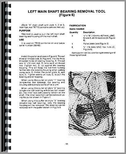
Figura 3: Detailed diagram illustrating the components and setup for the Left Main Shaft Bearing Removal Tool (Figure 6) from the service manual.
Other Maintenance and Repair Procedures
This manual covers a wide array of maintenance and repair tasks for the New Holland TR75 Combine. Key procedures include:
- Rotor Disassembly and Assembly: Step-by-step instructions for taking apart and reassembling the rotor components.
- Rotor Balance: Procedures for balancing the rotor to ensure smooth operation and prevent excessive vibration.
- Hydraulic System Service: Diagnostics and repair for the TR75/85 hydraulic system, including pressure testing.
- Transmission Service: Instructions for servicing the hydrostatic transmission and ground drive transmission.
- Final Drive Service: Detailed steps for maintaining and repairing the final drive components.
Each procedure includes specific tool requirements, safety precautions, and detailed steps to ensure correct execution.
Risoluzione dei problemi comuni
While this manual primarily focuses on service and repair, it implicitly aids in troubleshooting by providing correct assembly and operational parameters. Deviations from these parameters can often indicate a problem.
For specific troubleshooting, refer to the relevant sections detailing the expected performance and assembly of each component. For example, issues related to rotor vibration would direct the user to the "Rotor Balance Stand" section, while hydraulic system malfunctions would point to the "TR75/85 Hydraulic System Test Fittings" section.
Specifiche
This service manual provides detailed specifications for various components of the New Holland TR75 Combine. These specifications are crucial for proper repair and replacement of parts.
- Specifiche del dispositivo di fissaggio: Includes types, sizes, and grades of fasteners, such as the 1/2" x 18" UNC Grade 5 all-thread rod mentioned for bearing removal.
- Specifiche di coppia: Comprehensive charts for tightening bolts and nuts to their correct values.
- Component Dimensions: Critical dimensions for parts like bearings and shafts to ensure correct fitment.
- Capacità e tipologie di fluidi: (Refer to General Information section within the manual for details on lubricants and hydraulic fluids).
Always consult the specific section within the manual for the exact specifications required for the task at hand.