
DALY 200A Fan
DALY BMS 4S 12V 200A LiFePO4 Battery Protection Module User Manual
Model: 200A Fan | Brand: DALY
1. Introduzione
This manual provides essential instructions for the safe and effective installation, operation, and maintenance of your DALY BMS 4S 12V 200A LiFePO4 Battery Protection Module. This module is designed to optimize the performance and extend the lifespan of LiFePO4 battery packs by providing critical protection functions.

Figure 1: DALY BMS 4S 12V 200A LiFePO4 Battery Protection Module.
The DALY BMS offers comprehensive protection against overcurrent, overcharge, overdischarge, short circuit, and temperature fluctuations. It features double protection through injection patent technology and a patent shell, ensuring waterproof, dustproof, shockproof, and anti-static properties. High-quality components and precise acquisition accuracy contribute to its reliable performance.

Figure 2: Advanced technology features of the DALY BMS, highlighting its moisture-proof, anti-vibration, anti-oxidation properties, and compact, easy-to-install design.
Prodotto finitoview Video
Video 1: Un overview of the DALY BMS series, highlighting various models and key features such as shockproof design and MCU-level chip integration. This video provides a general introduction to the product line's capabilities and robust construction.
2. Informazioni sulla sicurezza
- Always wear appropriate personal protective equipment (PPE) when handling batteries and wiring.
- Assicurarsi che tutti i collegamenti siano sicuri e adeguatamente isolati per evitare cortocircuiti.
- Verify correct polarity before making any connections. Incorrect polarity can damage the BMS and battery.
- Do not attempt to disassemble or modify the BMS module.
- Keep the BMS away from water, heat, and flammable materials.
- If you are a novice, it is recommended to set the soldering iron temperature to about 350 degrees Celsius. Professional solder temperature is 420 degrees Celsius.
3. Lista di imballaggio

Figure 3: Contents of the DALY BMS package, including the BMS module, NTC sensor, sampling cable, and instruction manual.
Il pacchetto include i seguenti articoli:
- 3.2V LiFePO4 BMS (1 unit)
- NTC sensor (1 unit)
- Sampling cable (1 unit)
- Manuale di istruzioni (1 unità)
4. Specifiche
The DALY BMS 4S 200A LiFePO4 module is designed for 4-series LiFePO4 battery packs. Key specifications are detailed below:
- Dimensioni del prodotto: 4.72 x 9.25 x 2.05 pollici
- Peso dell'articolo: 3.97 libbre (1800 grammi)
- Ingresso volumetage: 3.75 Volts (per cell nominal)
- Marca: DALY
- Produttore: Dongguan Daly Electronics Co., Ltd
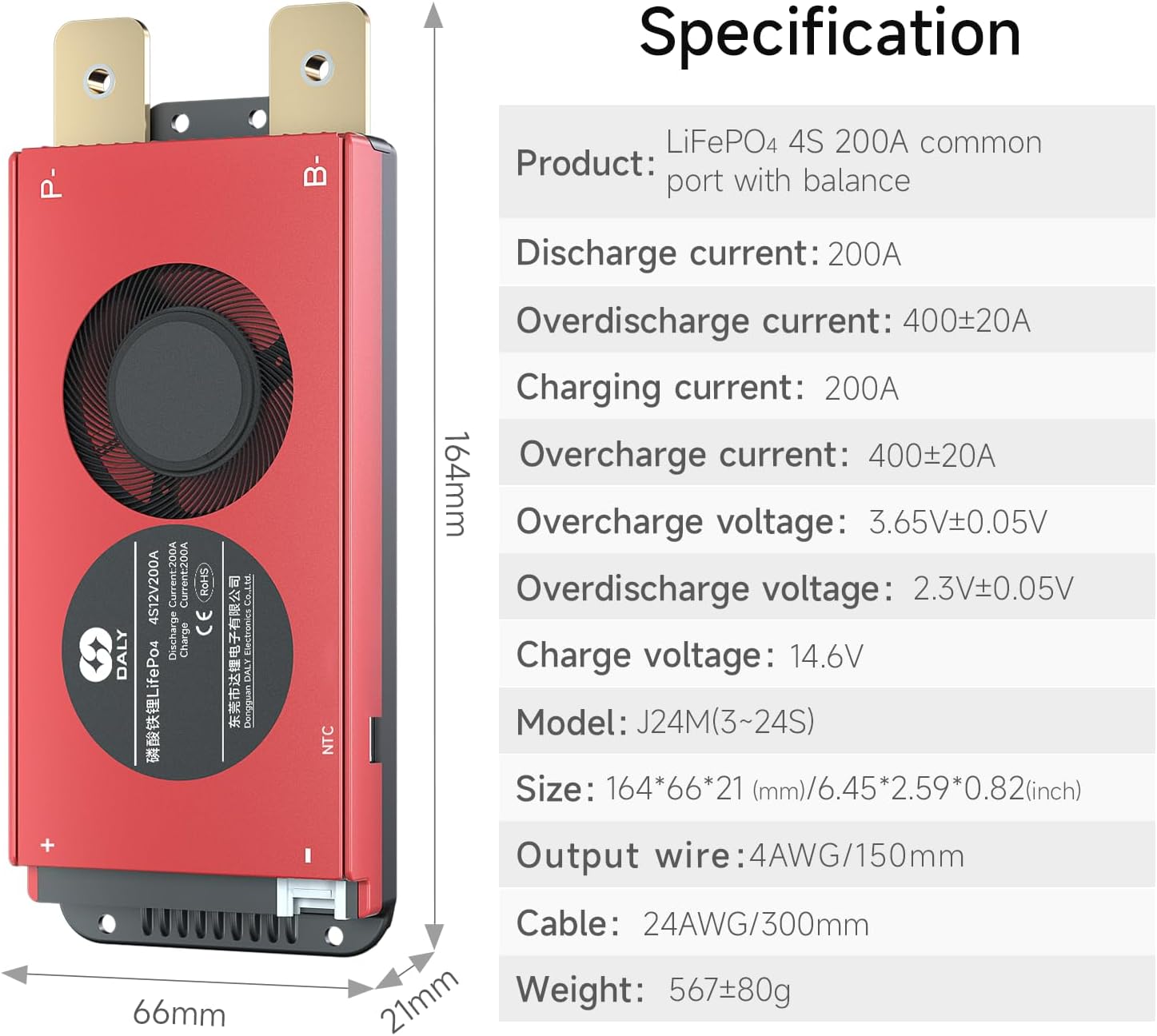
Figure 4: Detailed product specifications including discharge current, overcharge/overdischarge voltage, and physical dimensions.

Figure 5: Table showing detailed parameters for LiFePO4 4S BMS, including discharge current, inner resistance, charge voltage, and various protection thresholds.

Figure 6: Table showing detailed parameters for LiFePO4 4S Smart BMS. Note: This product is a Standard BMS, not a Smart BMS, and does not have communication functions.
5. Configurazione e installazione
Proper installation is crucial for the safe and optimal performance of your DALY BMS. Follow these steps carefully.
5.1. Prepare Materials
Video 2: This video demonstrates the necessary tools and materials for BMS wiring, including the BMS module, sampling cables, ceramic scissors, a multimeter, and a soldering iron. It also provides guidance on appropriate soldering temperatures for both novices and professionals.
5.2. Identifying Sampling punti
Before connecting the BMS, it is essential to correctly identify the sampling points on your battery pack. This ensures accurate voltage monitoraggio e bilanciamento.
Video 3: This video demonstrates how to determine the sampling points on a battery pack using a multimeter. It explains how to identify the total negative electrode (B-), the connection points between cells (B1, B2, B3, etc.), and the total positive electrode (B+). The video emphasizes checking voltage increases sequentially to confirm correct sampling point identification.
- Total Negative Electrode (B-): Il primo sampling point is the total negative electrode of the battery pack. Mark this as B-.
- Cell Connection Points (B1, B2, etc.): Subsequent sampling points are the connection points between the negative electrode of one cell and the positive electrode of the next cell in series. For example, B1 is the connection between the negative of the second cell and the positive of the first cell. Continue this for all cells.
- Total Positive Electrode (B+): Gli ultimi sampling point is the total positive electrode of the battery pack. Mark this as B+.
- Verification with Multimeter: Utilizzare un multimetro impostato su DC voltage to verify the sampling points. Place the black probe on B- and the red probe on each subsequent sampling point (B1, B2, ..., B+). The voltage reading should increase incrementally (approximately 3V-3.7V per cell for LiFePO4) as you move from B1 to B+. If the voltage does not increase sequentially, your sampling points are incorrect.
5.3. Collegamento del cablaggio
Una volta sampling points are identified and verified, proceed with wiring the BMS to the battery pack. The sampling cable has a black wire (B-) and several red wires (B1, B2, ..., B+).

Figure 7: A detailed wiring diagram illustrating the connection of the sampling cable and output wires to the battery pack and BMS. This diagram is crucial for correct installation.
- Solder Sampling Cables:
- Connect the black wire of the sampling cable to the total negative terminal (B-) of the battery pack.
- Connect the first red wire to the positive terminal of the first battery string (B1).
- Connect the second red wire to the positive terminal of the second battery string (B2), and so on, until all strings are connected.
- The last red wire connects to the total positive terminal (B+) of the battery pack.
- Controllare i collegamenti dei cavi: After connecting the cables, measure the voltage between two adjacent cables starting from the header. Ensure there are no wrong connections or missing connections.
- Collegare i cavi di uscita: Connect the B- wire of the BMS to the total negative terminal of the battery pack. Then, plug the sampling cable to the BMS. After activating the BMS, make sure that the voltage (batteria voltage) between B+ & B- and the voltage between P+ & P- are consistent.
5.4. Important Wiring Considerations
Video 4: This video highlights common errors during BMS wiring, including incorrect use of wiring harnesses, inserting the BMS before welding, virtual welding, and incorrect P-line/B-line connections. It provides visual examples of these mistakes and their potential consequences, such as component breakdown or short circuits.
- Utilizzare il cablaggio corretto: Ensure the wiring harness used is specifically designed for your DALY BMS model. Using incorrect wiring from different manufacturers can lead to poor contact or socket shedding.
- Connect BMS Last: Do not insert the BMS module until all battery wires are correctly welded and verified. Inserting the BMS prematurely, especially if wires are crossed, can lead to breakdown of internal components.
- Avoid Virtual Welding: Ensure all solder joints are strong and complete. Virtual welding (poor contact) can lead to voltage leakage and damage over time, potentially causing the electric car to stop functioning.
- Verify P-line and B-line: Incorrect connection of the P-line (output) and B-line (battery negative) can cause short circuits, burn out the sampling line, or even the entire protective plate. Always double-check these critical connections.
6. Funzionamento del BMS
Once installed, the DALY BMS operates automatically to protect your battery pack. It continuously monitors cell voltages, correnti e temperature.
- Protezione da sovraccarico: Impedisce che le celle vengano caricate oltre il loro volume sicurotage limite.
- Protezione da sovrascarica: Interrompe la scarica quando le celle raggiungono il loro volume minimo sicurotage, preventing damage.
- Protezione da sovracorrente: Limits current during discharge to prevent damage from excessive loads.
- Protezione da cortocircuito: Immediately cuts off current in case of a short circuit.
- Protezione della temperatura: Monitors battery temperature and intervenes if it exceeds safe operating limits.
- Balancing Function: Bilancia attivamente il volume cellularetages to ensure all cells are charged and discharged uniformly, extending battery life.
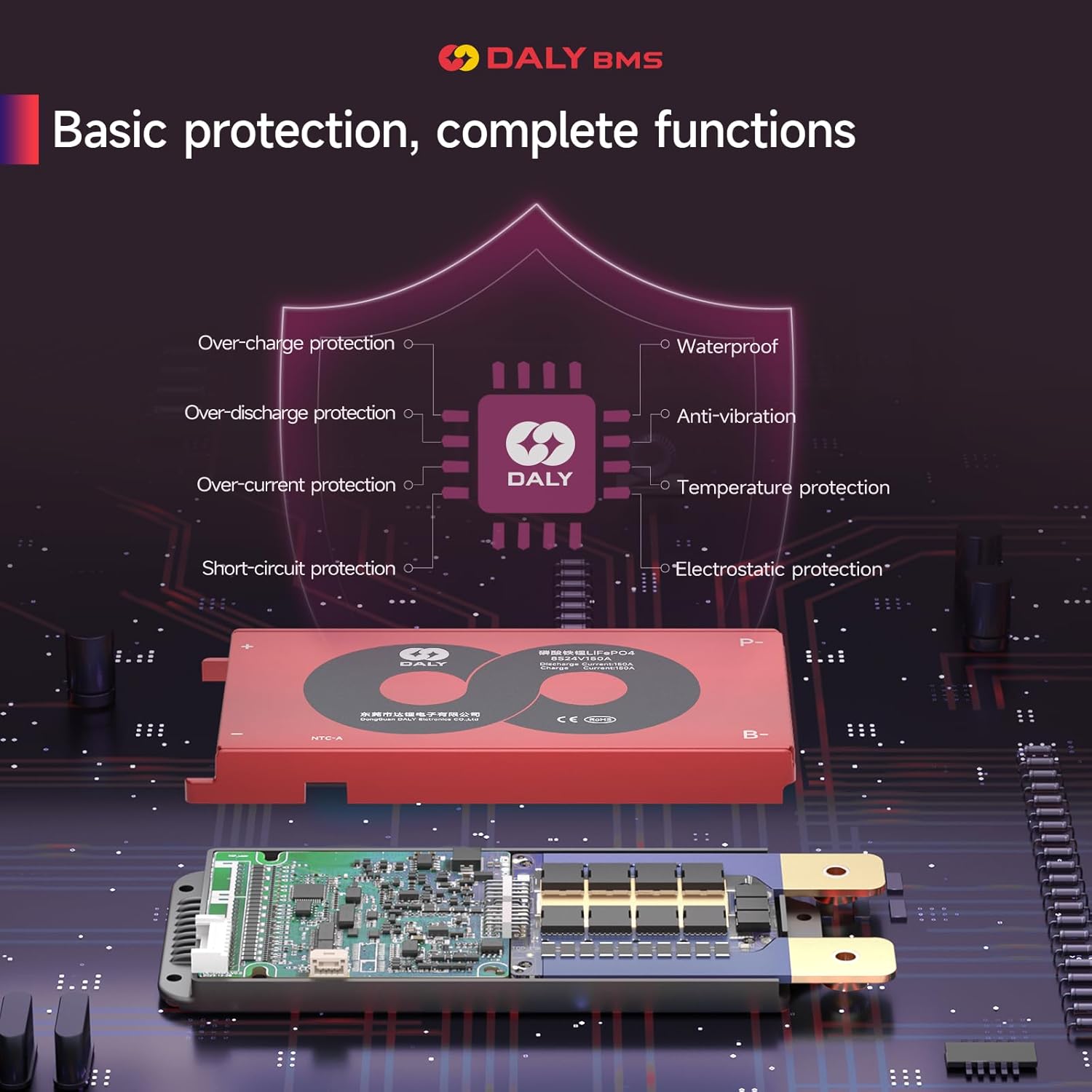
Figure 8: Visual representation of the basic protection functions provided by the DALY BMS, including over-charge, over-discharge, over-current, short-circuit, waterproof, anti-vibration, temperature, and electrostatic protection.
The BMS is suitable for various Li-batteries in diverse scenarios, including home energy storage, inverters, aerial work vehicles, marine energy storage, ATVs, floor sweepers, RVs, tour cars, low-speed vehicles, golf carts, and forklifts.

Figura 9: Esamples of various applications where the DALY BMS can be utilized, demonstrating its versatility across different battery types and usage environments.
7. Manutenzione
- Ispezionare regolarmente tutti i cablaggi e i collegamenti per verificare la presenza di segni di usura, corrosione o danni.
- Keep the BMS module clean and free from dust and debris.
- Ensure adequate ventilation around the BMS, especially for models with cooling fans, to prevent overheating.
- Avoid exposing the BMS to extreme temperatures or humidity.
8. Risoluzione Dei Problemi
If you encounter issues with your DALY BMS, consider the following common problems and solutions:
- Batteria non in carica/scarica:
- Check all wiring connections for correctness and secure contact. Refer to the wiring diagram.
- Verificare che sampling points are correctly identified and connected. Incorrect sampling can prevent proper operation.
- Ensure the BMS was inserted Dopo all battery wiring was completed and verified.
- Inspect for any signs of internal component damage on the BMS, which might occur from incorrect initial wiring.
- Surriscaldamento del BMS:
- Ensure proper ventilation around the BMS.
- Check if the load current exceeds the BMS's rated continuous discharge current.
- Volume cellulare incoerentetages (Balancing Issues):
- Conferma che la sampling wires are securely connected to each cell's positive terminal.
- Allow sufficient time for the balancing function to work, especially with new or heavily unbalanced packs.
For further assistance, please contact DALY customer service.
9. Garanzia e supporto
DALY provides a quality guarantee for its products. The package includes an instruction manual and the product is ISO/FCC/RoHS/PSE/CE APPROVED.
For any technical support or customer service inquiries, please contact DALY's online customer service. They offer 24-hour one-on-one customer service and lifetime technical support.
If you need smart BMS, active balancer, parallel module or other accessories, please contact online customer service.
Ask a question about this manual
Ask about setup, troubleshooting, compatibility, parts, safety, or missing instructions. Manuals+ will review the question and use this page’s manual context to help answer it.