
1. Introduzione
The EVTSCAN Peakmeter PM8213C is a portable digital multimeter designed for various electrical measurements. This instrument offers stable performance, high precision, and low power consumption, making it a reliable tool for both professional and DIY users. Its compact appearance and comprehensive features ensure accurate readings for voltage, current, resistance, continuity, non-contact voltage (NCV), frequency, and duty cycle.
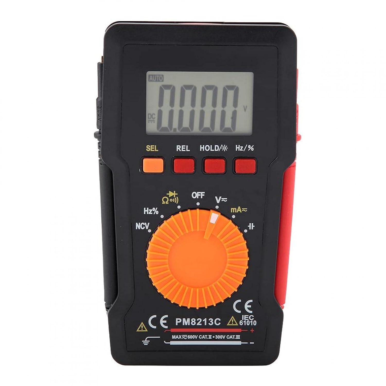
Figura 1: Fronte view of the EVTSCAN Peakmeter PM8213C Digital Multimeter.
2. Informazioni sulla sicurezza
To ensure safe operation and service of the meter, please read this manual carefully before use. Failure to observe safety warnings can result in serious injury or death. Always adhere to local and national safety codes.
- Non superare i limiti massimi di input per nessuna funzione.
- Prestare attenzione quando si lavora con voltagsuperiori a 30 V CA RMS, 42 V di picco o 60 V CC. Questi voltagrappresentano un rischio di scossa elettrica.
- Before measuring current, ensure the meter's test leads are connected to the correct input jacks and the function switch is set to the appropriate current range.
- Scollegare sempre i puntali di prova dal circuito prima di modificare la posizione dell'interruttore di funzione.
- Per garantire letture accurate, sostituire immediatamente la batteria quando appare l'indicatore di batteria scarica.
- Non utilizzare il misuratore se appare danneggiato o se il cavo di protezioneasing viene rimosso.
- Durante le misurazioni, tenere le mani e le dita dietro le barriere della sonda.
3. Prodotto finitoview
3.1. componenti
The PM8213C multimeter consists of the following main components:
- Schermo LCD: Mostra le letture delle misurazioni, le unità e gli indicatori di funzione.
- Pulsanti funzione: SEL (Select), REL (Relative), HOLD (Data Hold), Hz/% (Frequency/Duty Cycle).
- Interruttore rotante: Used to select the desired measurement function (e.g., V~, V-, Ω, Continuity, NCV, Hz%, mA~, A~).
- Jack di ingresso: Terminals for connecting test leads (COM, VΩHz, mA, A).
- Puntali di prova: Cavi rossi e neri per il collegamento al circuito in prova.
- Custodia protettiva: Provides protection for the meter.

Figure 2: Key features of the PM8213C Multimeter, including LCD screen and compact design.
3.2. Simboli sul display
Familiarize yourself with the symbols that may appear on the LCD display:
- AUTO: Auto-ranging mode is active.
- CC/CA: Direct Current / Alternating Current.
- V: Volt (VoltagE).
- Ω: Ohm (resistenza).
- Hz: Hertz (frequenza).
- %: Ciclo di lavoro.
- Valore NC: Volume senza contattotage rilevamento.
- TENERE: Data Hold function is active.
- REL: Modalità di misurazione relativa.
- Simbolo della batteria: Indica la carica della batteria bassa.
- OOL: Over-range indication.
4. Impostazione
4.1. Installazione della batteria
The PM8213C requires one CR2032 (3V) button cell battery for operation. The battery is typically not included in the package.
- Assicurarsi che il multimetro sia spento.
- Individuare il vano batterie sul retro del misuratore.
- Utilizzare uno strumento adatto (ad esempio un piccolo cacciavite) per aprire il coperchio del vano batteria.
- Insert the CR2032 battery, observing the correct polarity (+ and - markings).
- Riposizionare il coperchio del vano batteria e fissarlo.
4.2. Collegamento del puntale di prova
Connect the test leads to the appropriate input jacks before taking any measurements.
- Collegare il nero puntale di prova per il COM jack di ingresso (comune).
- Per la maggior parte delle misurazioni (voltage, resistance, frequency, duty cycle, continuity), connect the rosso puntale di prova per il VΩHz presa di ingresso.
- For current measurements (mA), connect the rosso puntale di prova per il mA presa di ingresso.
- For higher current measurements (A), connect the rosso puntale di prova per il A input jack (if available and distinct from mA). Note: The PM8213C typically uses a single current input for mA/A, check the dial for specific ranges.
5. Istruzioni per l'uso
5.1. Accensione/spegnimento
To turn the multimeter ON, rotate the function switch from the OFF position to any desired measurement function. To turn the multimeter OFF, rotate the function switch to the OFF position. The meter features an automatic power-off function after approximately 30 minutes of inactivity to conserve battery life.
5.2. Selezione della funzione
Use the rotary switch to select the primary measurement function. For functions with multiple modes (e.g., AC/DC voltage, continuity/diode), press the SEL pulsante per passare da una modalità all'altra.
5.3 Misurazione del volume CCtage (V-)
- Collegare il puntale di prova rosso alla presa VΩHz e il puntale di prova nero alla presa COM.
- Set the rotary switch to the V- position.
- Collegare i puntali di prova in parallelo alla tensione CCtagla sorgente o il componente che si desidera misurare.
- Leggi il vol.tage valore sul display LCD.
5.4. Misurazione del volume CAtage(V~)
- Collegare il puntale di prova rosso alla presa VΩHz e il puntale di prova nero alla presa COM.
- Impostare l'interruttore rotante sulla posizione V~.
- Collegare i puntali di prova in parallelo alla tensione CAtage sorgente o componente.
- Leggi il vol.tage valore sul display LCD.
5.5. Misurazione della resistenza (Ω)
- Prima di misurare la resistenza, assicurarsi che il circuito sia disattivato.
- Collegare il puntale di prova rosso alla presa VΩHz e il puntale di prova nero alla presa COM.
- Impostare il commutatore rotante sulla posizione Ω.
- Collegare i puntali di prova al componente di cui si desidera misurare la resistenza.
- Leggere il valore della resistenza sul display LCD.
5.6. Test di continuità (Ω))))
- Assicurarsi che il circuito sia disattivato.
- Collegare il puntale di prova rosso alla presa VΩHz e il puntale di prova nero alla presa COM.
- Set the rotary switch to the Continuity position (often shared with Resistance or Diode). Press SEL se necessario per selezionare la continuità.
- Collegare i puntali di prova al componente o al filo.
- Se esiste continuità (bassa resistenza), il misuratore emetterà un segnale acustico.
5.7. Vol. senza contattotage (NCV) Rilevamento
- Impostare l'interruttore rotante sulla posizione NCV.
- Move the top edge of the multimeter close to the conductor suspected of having AC voltage.
- Il misuratore indicherà la presenza di tensione alternatatage tramite un segnale acustico e/o un indicatore visivo (ad esempio, LED).
5.8. Misurazione della frequenza (Hz) e del ciclo di lavoro (%)
- Collegare il puntale di prova rosso alla presa VΩHz e il puntale di prova nero alla presa COM.
- Set the rotary switch to the Hz/% position.
- Collegare i puntali di prova in parallelo alla sorgente del segnale.
- Premere il tasto Hz/% button to toggle between frequency and duty cycle measurements.
- Leggere il valore sul display LCD.
5.9. Measuring Current (mA~, A~)
- AVVERTIMENTO: Non collegare mai il misuratore in parallelo a un voltage source when measuring current. This will blow the fuse and can damage the meter.
- Assicurarsi che il circuito sia disattivato.
- Collegare il puntale nero al jack COM.
- Per milliampere (mA) measurements, connect the red test lead to the mA jack. For ampere (A) measurements, connect the red test lead to the A jack (if separate).
- Set the rotary switch to the appropriate mA~ or A~ position.
- Open the circuit where you want to measure current and connect the meter in series with the load.
- Riattivare il circuito e leggere il valore corrente sul display LCD.
6. Manutenzione
6.1. Pulizia
Pulisci la custodia del misuratore con un pannoamp panno e detergente delicato. Non utilizzare abrasivi o solventi. Mantenere i terminali di ingresso liberi da sporco e umidità.
6.2. Sostituzione della batteria
When the low battery indicator appears on the display, replace the CR2032 battery promptly to ensure accurate measurements.
- Turn the multimeter OFF and disconnect all test leads.
- Aprire il coperchio del vano batteria sul retro dello strumento.
- Rimuovere la vecchia batteria CR2032.
- Insert a new CR2032 (3V) button cell battery, ensuring correct polarity.
- Chiudere saldamente il coperchio del vano batterie.
6.3. Sostituzione del fusibile
If the current measurement function stops working, the fuse may need replacement. The fuse specification is F 400mA/250V.
- Turn the multimeter OFF and disconnect all test leads.
- Open the meter's casing (refer to the battery replacement section for access, or consult the full service manual if necessary).
- Locate the blown fuse.
- Carefully remove the old fuse and replace it with a new fuse of the exact same type and rating (F 400mA/250V).
- Reassemble the meter's casing in modo sicuro.
7. Risoluzione Dei Problemi
If the meter does not function correctly, check the following points before seeking service:
- Nessun display o display debole: Controllare l'installazione della batteria e sostituirla se necessario.
- Letture errate: Ensure test leads are correctly connected to the appropriate input jacks and the rotary switch is set to the correct function and range. Check battery level.
- Misurazione della corrente non funzionante: Check and replace the fuse if blown. Ensure test leads are connected in series with the circuit.
- "OOL" displayed: Il valore misurato supera l'intervallo selezionato. Passare a un intervallo superiore o assicurarsi che l'ingresso rientri nelle capacità del misuratore.
8. Specifiche
| Altitudine | Meno di 2000 m |
| Temperatura di esercizio | Temperatura ambiente: da 0 a 40 °C |
| Umidità di esercizio | <80% RH (not considered at <10 °C) |
| Temperatura di conservazione | Temperatura -10 ~ 60 °C |
| Umidità di stoccaggio | <70% RH (remove batteries) |
| Coefficiente di temperatura | 0.1 precision/°C |
| Vol. massimo consentitotage (Input to Ground) | 600V DC o AC rms |
| Protezione Fusibile | F 400 mA/250 V |
| Samptasso di ling | Circa 3 volte al secondo |
| Spegnimento automatico | Circa 30 minuti |
| Display | Maximum 3999 counts |
| Display fuori scala | "OOL" |
| Alimentazione elettrica | CR2032 (3V) button cell battery |
| Peso | Approximately 120 - 142 g |
| Dimensioni (L x P x A) | 127 x 70 x 12.5 mm (circa 12.8 x 7.5 x 1.3 cm) |
8.1. Volume CCtage (PM8213C)
| Allineare | Risoluzione | Precisione |
|---|---|---|
| 4 Volt | 0.001 Volt | ±(0.1% + 3 cifre) |
| 40 Volt | 0.01 Volt | ±(0.1% + 3 cifre) |
| 400 Volt | 0.1 Volt | ±(0.1% + 3 cifre) |
| 600 Volt | 1 Volt | ±(0.1% + 3 cifre) |
8.2. Contenuto della confezione
- 1 x Digital Multimeter (PM8213C)
- 2 x Test Leads
- 1 x Custodia protettiva
9. Garanzia e supporto
Per informazioni sulla garanzia o assistenza tecnica, contattare direttamente il venditore o il produttore. Conservare la ricevuta d'acquisto come prova d'acquisto.