
1. Introduzione
The Sunshine DT-17N Digital Multimeter is a versatile and reliable tool designed for accurate electrical measurements. It is particularly suitable for phone repair technicians and general electronics work, capable of measuring various electrical parameters including voltage, current, resistance, capacitance, and temperature. Its compact design and user-friendly features make it an essential tool for diagnosing and repairing electronic devices.

Figure 1: The Sunshine DT-17N Digital Multimeter, demonstrating its compact size for portability.
2. Informazioni sulla sicurezza
To ensure safe operation and prevent damage to the meter, please read and follow all safety instructions carefully. This multimeter features double insulation protection for enhanced user safety.
- Always ensure the test leads are in good condition and properly connected before taking measurements.
- Non applicare voltage or current that exceeds the maximum rated values for each range.
- Never use the multimeter if it appears damaged or if the test leads are frayed.
- Siate cauti quando lavorate con voltagsuperiori a 30 V CA RMS, 42 V di picco o 60 V CC, poiché rappresentano un rischio di scossa elettrica.
- Scollegare sempre l'alimentazione dal circuito e scaricare l'alto volumetagcondensatori prima di misurare la resistenza, la continuità o i diodi.
- Per garantire letture accurate, sostituire tempestivamente la batteria quando appare l'indicatore di batteria scarica.
3. Prodotto finitoview
3.1. Componenti del multimetro

Figura 2: Fronte view of the DT-17N Multimeter, highlighting its main display and controls.
3.2. Caratteristiche dello schermo
The DT-17N features a large LCD display with a backlight, ensuring clear readability in various lighting conditions.

Figure 3: The multimeter's LCD display with its backlight feature, improving visibility in low-light environments.
- Ampio display LCD: Provides clear numerical readings.
- Retroilluminazione: Improves visibility in dark or low-light conditions. Activated by pressing and holding the HOLD button.
- Unità di misura: Displays the appropriate unit (e.g., V, A, Ω, °C/°F).
- Stato della batteria: Indica il livello attuale della batteria.
- Automatic Polarity Display: Shows positive or negative polarity automatically.
3.3. Controls and Input Ports
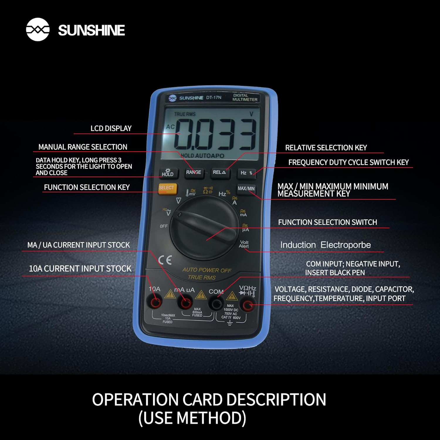
Figura 4: dettagliata view of the multimeter's controls and input ports with their respective functions.
- Interruttore di funzione rotante: Utilizzato per selezionare la funzione di misurazione desiderata (ad esempio, Voltage, Corrente, Resistenza, Temperatura).
- Pulsante SELEZIONA: Toggles between different measurement modes within a single rotary switch position (e.g., AC/DC voltage, Diodo/Continuità).
- Pulsante ATTESA: Freezes the current reading on the display. Press and hold to activate/deactivate the backlight.
- Pulsante GAMMA: Allows manual selection of measurement ranges, overriding the automatic ranging feature.
- RELA Button (Relative Selection Key): Misura la differenza tra un valore di riferimento memorizzato e la lettura corrente.
- Hz % Button (Frequency Duty Cycle Switch Key): Toggles between frequency and duty cycle measurements.
- Pulsante MAX/MIN: Visualizza il valore massimo o minimo misurato durante una sessione di misurazione.
- Porta di ingresso VΩHz: Collegare il puntale di prova rosso per voltage, resistance, frequency, capacitance, diode, and temperature measurements.
- Porta di ingresso COM: Connect the black test lead (common ground) for all measurements.
- mA/uA Input Port: Connect the red test lead for measuring small currents (milliamperes and microampere).
- Porta di ingresso 10A: Connect the red test lead for measuring large currents (up to 10 Ampere).
- Volt Alert (NCV): Volume senza contattotage funzione di rilevamento.
4. Impostazione
4.1. Installazione della batteria
The DT-17N is battery-powered. To install or replace the battery:
- Assicurarsi che il multimetro sia spento.
- Individuare il coperchio del vano batterie sul retro dell'unità.
- Svitare la/le vite/i di fissaggio e rimuovere il coperchio.
- Insert the new battery, observing correct polarity (+ and -).
- Richiudere il coperchio del vano batteria e fissarlo con la/le vite/i.
4.2. Collegamento dei puntali di prova
Always connect the black test lead to the COM input jack. Connect the red test lead to the appropriate input jack based on the measurement you intend to perform:
- Per voltage, Resistance, Capacitance, Frequency, Diode, and Temperature measurements: Connect the red test lead to the VΩHz cricco.
- For Current measurements (mA/uA): Connect the red test lead to the mA/uA cricco.
- For High Current measurements (10A): Connect the red test lead to the 10A cricco.
5. Istruzioni per l'uso
The Sunshine DT-17N features automatic identification for most ranges, simplifying operation. Use the rotary switch to select the primary function and the SELECT button to toggle sub-functions.
5.1. Misurazione del volumetage (CA/CC)
- Ruotare il selettore in posizione V posizione.
- Se necessario, premere il tasto SELEZIONARE button to toggle between AC (~) and DC (—) voltage.
- Collegare il puntale nero a COM jack e il puntale rosso al VΩHz cricco.
- Collegare le sonde di prova in parallelo al circuito o al componente che si desidera misurare.
- Leggi il vol.tage valore sul display.

Figure 5: The multimeter showing a DC millivolt measurement on its display.
5.2. Misurazione della corrente (AC/DC)
Attenzione: Never connect the multimeter in parallel when measuring current, as this can damage the meter and the circuit. Always connect in series.
- Ruotare il selettore in posizione mA/uA or 10A posizione, a seconda della corrente prevista.
- Se necessario, premere il tasto SELEZIONARE button to toggle between AC (~) and DC (—) current.
- Collegare il puntale nero a COM jack. Collegare il puntale rosso al mA/uA or 10A jack accordingly.
- Aprire il circuito e collegare le sonde di prova in serie con il carico.
- Leggere il valore corrente sul display.
5.3. Misurare la resistenza
- Ruotare il selettore in posizione Ω posizione.
- Collegare il puntale nero a COM jack e il puntale rosso al VΩHz cricco.
- Assicurarsi che il circuito sia disattivato e che tutti i condensatori siano scarichi.
- Collegare le sonde di prova al componente per misurarne la resistenza.
- Leggere il valore di resistenza sul display.
5.4. Misurazione della capacità
- Ruotare il selettore in posizione Capacità symbol (often shared with diode/continuity).
- Premere il tasto SELEZIONARE button until the capacitance mode is active.
- Collegare il puntale nero a COM jack e il puntale rosso al VΩHz cricco.
- Prima di collegare le sonde di prova, assicurarsi che il condensatore sia completamente scarico.
- Collegare le sonde di prova attraverso il condensatore.
- Leggere il valore della capacità sul display.
5.5. Measuring Frequency / Duty Cycle
- Ruotare il selettore in posizione Hz% posizione.
- Premere il tasto Hz% pulsante per alternare tra frequenza (Hz) e ciclo di lavoro (%).
- Collegare il puntale nero a COM jack e il puntale rosso al VΩHz cricco.
- Collegare le sonde di prova in parallelo alla sorgente del segnale.
- Leggere il valore della frequenza o del ciclo di lavoro sul display.
5.6. Misurazione della temperatura
The DT-17N can measure temperature using a K-type thermocouple (not always included, check package contents).

Figura 6: Esample of temperature measurement using the DT-17N Multimeter with a thermocouple.
- Ruotare il selettore in posizione ° C / ° F posizione.
- Se necessario, premere il tasto SELEZIONARE button to choose between Celsius or Fahrenheit.
- Collegare la termocoppia di tipo K al VΩHz E COM jack, osservando la polarità.
- Posizionare la punta della termocoppia sull'oggetto di cui si desidera misurare la temperatura o al suo interno.
- Leggere il valore della temperatura sul display.
5.7. Test diodo e continuità
- Ruotare il selettore in posizione Diodo/Continuità simbolo.
- Premere il tasto SELEZIONARE pulsante per passare dal test diodo al test di continuità.
- Collegare il puntale nero a COM jack e il puntale rosso al VΩHz cricco.
- For Diode Test: Connect the probes across the diode. The display will show the forward voltage goccia. Invertire le sonde per verificare la presenza di un circuito aperto.
- For Continuity Test: Connect the probes across the circuit or component. A beep indicates continuity (low resistance).
5.8. Vol. senza contattotage (NCV) Rilevamento
The NCV function allows detection of AC voltage senza contatto diretto con i conduttori.
- Ruotare il selettore in posizione VNC position (often indicated by a Volt Alert symbol).
- Move the top part of the multimeter near the conductor.
- The meter will beep and/or flash an indicator light if AC voltage viene rilevato.
5.9. Mantenimento dei dati e retroilluminazione
- Data Hold: Premere il tasto PRESA Premere brevemente il pulsante per congelare la lettura corrente sul display. Premere nuovamente per rilasciare.
- Retroilluminazione: Premere e tenere premuto il tasto PRESA per circa 3 secondi per accendere o spegnere la retroilluminazione del display.
5.10. Misurazione MAX/MIN
This function records the maximum and minimum values measured during a session.
- Selezionare la funzione di misura desiderata (ad esempio, VoltagE).
- Premere il tasto Massimo/minimo button. The display will show 'MAX' and the maximum value recorded.
- Premere Massimo/minimo again to cycle to 'MIN' and view the minimum value.
- Premere e tenere premuto Massimo/minimo per uscire da questa modalità.
6. Manutenzione
Una corretta manutenzione garantisce la longevità e la precisione del multimetro.
6.1. Pulizia
Pulisci la custodia con l'adamp panno e detergente delicato. Non utilizzare abrasivi o solventi. Assicurarsi che il misuratore sia completamente asciutto prima dell'uso.
6.2. Sostituzione della batteria
Refer to Section 4.1 for battery replacement instructions. Always use the specified battery type.
6.3. Holster Care
The multimeter is protected by a thick rubber shockproof holster, designed for durability and a non-slip grip. Keep the holster clean and free from debris.

Figure 7: The durable rubber holster provides protection and a comfortable grip for the multimeter.
7. Risoluzione Dei Problemi
If you encounter issues with your DT-17N multimeter, refer to the table below for common problems and solutions.
| Problema | Possibile causa | Soluzione |
|---|---|---|
| Nessun display o display poco luminoso | Low or dead battery; Poor battery contact | Replace battery; Check battery contacts |
| Letture errate | Wrong function selected; Improper test lead connection; Damaged test leads; Out of range | Select correct function; Ensure leads are in correct jacks; Replace leads; Select higher range or check specifications |
| Nessun segnale acustico di continuità | Circuit resistance too high; Continuity mode not selected | Ensure resistance is below threshold; Press SELECT to enter continuity mode |
| Fuse blown (for current measurements) | Overcurrent applied | Replace fuse with specified type and rating; Ensure correct current measurement procedure |
8. Specifiche
Technical specifications for the Sunshine DT-17N Digital Multimeter.
| Caratteristica | Specificazione |
|---|---|
| Modello | Modello DT-17N |
| Tipo di misurazione | Multimetro |
| Display | 5999 (5 5/6) counts, Automatic Polarity Display, Backlit LCD |
| Samptasso di ling | Circa 3 volte al secondo |
| Fonte di alimentazione | Alimentato a batteria |
| Volume di esercizio minimotage | 3 Volt (CC) |
| Campo di misurazione della temperatura | da 0°C a 1000°C (da 32°F a 1832°F) |
| Induction Electroprobe Function | Yes (NCV) |
| Doppia conversione integrale A/D | SÌ |
| Dimensioni dell'articolo | 5.51 x 2.76 x 1.18 pollici |
| Peso dell'articolo | 0.55 chilogrammi |
| Colore | Blu |
9. Garanzia e supporto
9.1. Informazioni sulla garanzia
This product comes with a warranty of 3 mesi dalla data di acquistoSi prega di conservare la prova d'acquisto per eventuali reclami in garanzia. La garanzia copre i difetti di fabbricazione in condizioni di normale utilizzo.
9.2. Assistenza clienti
For technical assistance or inquiries regarding your Sunshine DT-17N Digital Multimeter, please contact your retailer or the manufacturer's customer service department. Refer to your purchase documentation for specific contact details.