1. Introduzione
This manual provides detailed instructions for the installation, operation, and maintenance of your BooiParts G31T-LM V1.0 Desktop Motherboard. Please read this manual thoroughly before proceeding with installation to ensure proper setup and to prevent damage to the components.
2. Informazioni sulla sicurezza
- Scollegare sempre l'alimentatore dalla presa a muro prima di installare o rimuovere qualsiasi componente.
- Wear an anti-static wrist strap or frequently touch a grounded metal object to discharge static electricity before handling the motherboard or other components. Static electricity can damage sensitive electronic parts.
- Maneggiare la scheda madre tenendola per i bordi per evitare di toccare i componenti sensibili.
- Prima di accendere il sistema, assicurarsi che tutti i cavi siano collegati correttamente e saldamente.
- Non esporre la scheda madre a umidità o temperature estreme.
3. Contenuto della confezione
Verifica che tutti gli articoli siano presenti nel pacco. Se alcuni articoli risultano mancanti o danneggiati, contatta il rivenditore.
- BooiParts G31T-LM V1.0 Desktop Motherboard
- I/O Shield (may be included)
- SATA Data Cable (may be included)
- Manuale dell'utente (questo documento)
4. Prodotto finitoview
The BooiParts G31T-LM V1.0 motherboard is designed for Intel LGA 775 processors and supports DDR2 memory. Below are key components and their locations.
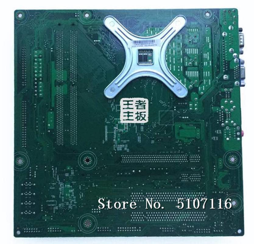
Figura 4.1: Superiore view of the BooiParts G31T-LM V1.0 motherboard. This image highlights the central LGA 775 CPU socket, two DDR2 RAM slots to its right, and various expansion slots (PCIe and PCI) below the CPU area. Power connectors and SATA ports are also visible along the edges.

Figura 4.2: Angolato view of the BooiParts G31T-LM V1.0 motherboard. This perspective provides a clearer view of the rear I/O panel, including PS/2 ports, serial port, VGA output, USB ports, Ethernet port, and audio jacks. Key components like the chipset heatsink and power delivery components are also visible.
4.1 componenti chiave
- Socket CPU LGA 775: For Intel Core 2 Duo and Pentium D processors.
- Slot DIMM DDR2: Two slots supporting up to 8GB DDR2 memory.
- Slot PCI Express: Per schede grafiche.
- Slot PCI: Per altre schede di espansione.
- Porta SATA: Per collegare dispositivi di archiviazione.
- Pannello I/O posteriore: Includes PS/2 ports, USB ports, VGA, LAN, and audio jacks.
5. Impostazione
5.1 Preparazione
- Assicurati che il case del tuo computer sia compatibile con le schede madri Micro-ATX.
- Gather all necessary components: CPU, CPU cooler, DDR2 RAM, power supply, storage devices, and graphics card (if not using integrated graphics).
5.2 Installazione della CPU
- Individua il socket LGA 775 sulla scheda madre.
- Sollevare la leva di caricamento e aprire il coperchio del socket della CPU.
- Carefully align the CPU with the socket, ensuring the notches on the CPU match the keys on the socket. Do not force the CPU into place.
- Chiudere il coperchio della presa e spingere verso il basso la leva di carico finché non si blocca in posizione.
5.3 Installazione del dissipatore della CPU
Apply thermal paste to the CPU if not pre-applied on the cooler. Install the CPU cooler according to its manufacturer's instructions, ensuring it is securely fastened and the fan cable is connected to the CPU_FAN header on the motherboard.
5.4 Installazione RAM
- Aprire le clip su entrambe le estremità degli slot DIMM DDR2.
- Allineare il modulo RAM con lo slot, assicurandosi che la tacca sul modulo corrisponda alla chiave nello slot.
- Premere con decisione su entrambe le estremità del modulo RAM finché le clip non scattano in posizione.
5.5 Installazione della scheda madre nel case
- Installare la schermatura I/O nell'apertura posteriore del case del computer.
- Carefully place the motherboard into the case, aligning the screw holes on the motherboard with the standoffs in the case.
- Fissare la scheda madre con le viti. Non stringere eccessivamente.
5.6 Collegamento dell'alimentazione
- Collegare il connettore di alimentazione ATX a 24 pin dell'alimentatore al connettore corrispondente sulla scheda madre.
- Connect the 4-pin ATX 12V power connector (CPU power) to its header near the CPU socket.
5.7 Collegamento dei dispositivi di archiviazione
Connect your SATA storage devices (HDD/SSD) to the SATA port on the motherboard using a SATA data cable. Connect the power cable from your power supply to the storage device.
5.8 Collegamento dei connettori del pannello frontale
Connect the front panel cables (Power SW, Reset SW, HDD LED, Power LED, USB, Audio) from your case to the corresponding headers on the motherboard. Refer to the motherboard's silkscreen labels for correct pin orientation.
5.9 Collegamento delle periferiche
Collegare la tastiera, il mouse, il monitor e le altre periferiche alle porte appropriate sul pannello I/O posteriore.
6. Istruzioni per l'uso
6.1 Primo avvio
After completing all connections, turn on your power supply and press the power button on your computer case. The system should power on, and you should see a display on your monitor. If not, refer to the Troubleshooting section.
6.2 Configurazione BIOS/UEFI
Durante l'avvio, premere il tasto designato (solitamente DEL or F2) to enter the BIOS/UEFI setup utility. Here you can configure system settings, boot order, and monitor hardware status.
7. Manutenzione
- Pulizia: Pulire regolarmente la scheda madre e i componenti dalla polvere utilizzando aria compressa. Assicurarsi che il sistema sia spento e scollegato prima di procedere alla pulizia.
- Aggiornamenti del BIOS: Controllare il produttore websito per gli aggiornamenti del BIOS. Aggiornare il BIOS solo se necessario e seguire attentamente le istruzioni per evitare l'instabilità del sistema.
- Gestione dei cavi: Assicurarsi che i cavi siano disposti in modo ordinato per migliorare il flusso d'aria ed evitare interferenze.
8. Risoluzione Dei Problemi
8.1 Nessun potere
- Check if the power supply is switched on and properly connected to the motherboard (24-pin and 4-pin connectors).
- Assicurarsi che il cavo dell'interruttore di alimentazione del pannello frontale sia collegato correttamente al connettore della scheda madre.
- Testare l'alimentatore con un altro sistema o con un tester per alimentatori.
8.2 Nessuna visualizzazione
- Verify that the monitor is connected to the correct video output (onboard VGA or discrete graphics card).
- Reinstallare i moduli RAM. Una RAM installata in modo errato è una causa comune di assenza di visualizzazione.
- If using a discrete graphics card, ensure it is properly seated in its PCIe slot and has adequate power connected.
- Prova ad avviare il computer con una sola RAM.
8.3 Instabilità/arresti anomali del sistema
- Controlla le temperature di CPU e GPU. Il surriscaldamento può causare instabilità.
- Assicurarsi che tutti i driver siano aggiornati.
- Eseguire strumenti di diagnostica della memoria per verificare la presenza di RAM difettosa.
- Verificare l'alimentazione elettricatage è sufficiente per tutti i componenti.
9. Specifiche
The following table outlines the key specifications for the BooiParts G31T-LM V1.0 Motherboard.
| Caratteristica | Specificazione |
|---|---|
| Marca | BooiParts |
| Nome del modello | G31T-LM V1.0 |
| Presa CPU | LGA775 |
| Processori compatibili | Intel Core 2 Duo, Intel Pentium D |
| Tipo di chipset | Intel G31 |
| Tecnologia della memoria RAM | DDR2 |
| Slot di memoria disponibili | 2 |
| Capacità di archiviazione della memoria (max) | 8 GB |
| Interfaccia della scheda grafica | PCI-Espresso |
| Total SATA Ports | 1 |
| Total PCIe Ports | 2 |
| Tipo di connettore di alimentazione principale | 24 pin |
| Dispositivi compatibili | Personal computer |
| Numero di modello | T4900V 53Y3282 45C2882 |
10. Garanzia e supporto
Per informazioni sulla garanzia e assistenza tecnica, consultare la documentazione fornita con l'acquisto o contattare il rivenditore. Conservare la prova d'acquisto per eventuali reclami in garanzia.