Introduzione
This manual provides essential information for the safe and effective use of the Velleman WMPC124 1A Power Supply Module. This module is designed to convert an AC or DC input voltage into a stable, adjustable DC output voltage, suitable for various electronic projects and experiments. Please read these instructions carefully before installation and operation.
Istruzioni di sicurezza
- Scollegare sempre l'alimentazione prima di effettuare qualsiasi collegamento o regolazione al modulo.
- Assicurarsi che il volume di ingressotage and current ratings do not exceed the module's specifications.
- Observe correct polarity for DC input and output connections.
- Avoid short circuits on the output terminals.
- This module is intended for use by individuals with basic knowledge of electronics. If unsure, seek professional assistance.
- Non esporre il modulo a umidità, temperature estreme o ambienti corrosivi.
Prodotto finitoview
The Velleman WMPC124 is a compact, assembled, and tested power supply module. It features input and output screw terminals for secure wiring and a potentiometer for adjusting the output voltage.
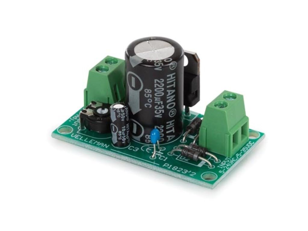
Figura 1: in alto view of the WMPC124 module. Note the input terminals on the right, output terminals on the left, and the voltage adjustment potentiometer at the bottom-left.

Figura 2: Angolato view of the WMPC124 module, showing component layout.
Specifiche
| Caratteristica | Valore |
|---|---|
| Volume di uscita minimotage | 1.2 Volt |
| Corrente di uscita massima | 1 A |
| Volume di uscita massimotage | 30 VCC |
| Volume massimo in ingressotage | 24 VCA o 35 VCC |
| Livello di abilità | Assembled and Tested |
| Cosatage | 15 watt |
| Ingresso volumetage (CA) | Up to 24 Volts (AC) |
| Amprabbia | 1 Amps (Uscita) |
| Volume di uscitatage (CC) | Regolabile da 1.2 V a 30 V |
| Dimensioni | Dimensioni: 3.5 x 7.5 x 15.5 cm |
| Peso | 60 grammi |
Impostare
1. Transformer Selection
The WMPC124 module requires an external AC transformer or a DC power source. The choice of transformer depends on the desired DC output voltage. Refer to the table below for guidance:

Figure 3: Transformer rating guide.
Recommended Transformers:
- For 3-6VDC output: 9Vac transformer (e.g., 109010C: OPEN-FRAME TRANSFORMER 10.8 VA 1 x 9 V~ 1200 mA max.)
- For 6-9VDC output: 12Vac transformer (e.g., 112012C: OPEN-FRAME TRANSFORMER 12 VA 1 x 12 V~ 1000 mA max.)
- For 9-12VDC output: 15Vac transformer
- For 12-15VDC output: 18Vac transformer
- For 15-21VDC output: 24Vac transformer (e.g., 212024C: OPEN-FRAME TRANSFORMER 24 VA 2 x 12 V~ 1000 mA max.)
2. Collegamenti elettrici
- Connessione di ingresso: Connect your chosen AC transformer (or DC power source) to the INGRESSO screw terminals on the right side of the module. Ensure the input voltage does not exceed 24 VAC or 35 VDC. For AC input, polarity is not critical. For DC input, observe the '+' and '-' markings if present, though the module's rectifier bridge allows for some tolerance.
- Connessione di uscita: Connect your load (e.g., DC motor, low-voltage light bulb, project circuit) to the PRODUZIONE screw terminals on the left side of the module. Observe the '+' and '-' polarity markings carefully.
3. Initial Adjustment
Before applying power to your load, it is recommended to set the output voltage to its minimum. Use a small screwdriver to turn the potentiometer (labeled 'Vout Adj.') fully counter-clockwise. This will set the output to approximately 1.2V.
Funzionamento del modulo
- Accensione: Once all connections are secure and verified, apply power to the input terminals.
- Regolazione del volume di uscitatage: Connect a multimeter to the output terminals to monitor the voltage. Slowly turn the potentiometer clockwise to increase the output voltage to your desired level (between 1.2V and 30V).
- Limitazione corrente: The module is rated for a maximum output current of 1A. Do not exceed this limit to prevent damage to the module or connected devices.
- Spegni: Disconnect the input power when the module is no longer needed.
Manutenzione
- Mantenere il modulo pulito e privo di polvere e detriti. Utilizzare un panno morbido e asciutto per la pulizia.
- Regularly inspect all wiring connections to ensure they are tight and secure.
- Quando non viene utilizzato, conservare il modulo in un ambiente asciutto e fresco.
- Evitare urti o vibrazioni eccessive.
Risoluzione dei problemi
- Nessuna uscita Voltage:
- Check if input power is correctly applied and within specifications.
- Verify input and output wiring for correct connections and polarity.
- Ensure the potentiometer is not set to its absolute minimum (though it should still provide ~1.2V).
- Inspect for any visible damage to components (e.g., burnt resistors, bulging capacitors).
- Volume di uscita erratotage:
- Recalibrate the output voltage using a multimeter and the potentiometer.
- Assicurare il volume di inputtage is stable and sufficient for the desired output.
- Surriscaldamento del modulo:
- Reduce the load current to stay within the 1A maximum.
- Assicurare un'adeguata ventilazione attorno al modulo.
- Verificare che il volume di ingressotage is not excessively high for the desired output, leading to higher power dissipation.
Garanzia e supporto
For warranty information or technical support, please refer to the documentation provided with your purchase or contact your retailer or the manufacturer, Velleman, directly. Keep your proof of purchase for any warranty claims.
Velleman Contact Information: Visita il sito ufficiale Velleman websito per il supporto e i dettagli di contatto più aggiornati.