
1. Introduzione
This manual provides detailed instructions for the installation, operation, and maintenance of your Chieftec BE-10B-300 Small Form Factor (SFF) computer case. Please read this manual thoroughly before beginning assembly to ensure proper setup and safe usage. Keep this manual for future reference.
2. Informazioni sulla sicurezza
- Always disconnect the power cord from the wall outlet before opening the computer case or performing any installation or maintenance.
- Garantire un'adeguata messa a terra per evitare scosse elettriche.
- Handle all components with care to avoid damage from electrostatic discharge (ESD). Consider using an anti-static wrist strap.
- Keep the case away from sources of heat, direct sunlight, and moisture.
- Do not block ventilation openings to ensure adequate airflow and prevent overheating.
3. Contenuto della confezione
Verify that all components are present in the package. If any items are missing or damaged, contact your retailer.
- Chieftec BE-10B-300 SFF Computer Case
- Cavo di alimentazione
- Accessory Kit (screws, standoffs, cable ties, small bracket)
- Manuale dell'utente (questo documento)

Figure 3.1: Included accessory kit with various screws, a power cable, and a small mounting bracket.
4. Prodotto finitoview
The Chieftec BE-10B-300 is a compact Small Form Factor (SFF) computer case designed for Mini ATX and Micro ATX motherboards. It features a sleek black design and includes a 300W power supply. The case supports various storage configurations and offers convenient front panel connectivity.
4.1 Esterno Views

Figura 4.1: Fronte view of the Chieftec BE-10B-300 case, showcasing the optical drive bay, power button, and front I/O ports in a vertical setup.

Figura 4.2: Fronte angolato view of the case, highlighting the textured front panel and accessible ports.

Figura 4.3: in alto view of the case when oriented horizontally, showing the smooth top panel.
4.2 Disposizione interna
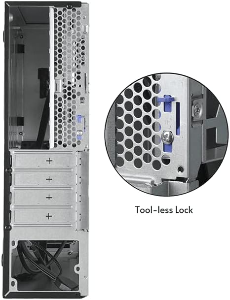
Figura 4.4: Interno view of the case, illustrating the motherboard mounting area and the pre-installed cooling fan.

Figura 4.5: Un altro interno view, detailing the drive bay structure and internal cabling.
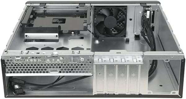
Figura 4.6: Posteriore view of the case, showing expansion slots and a close-up of the tool-less lock mechanism for easy component installation.
5. Guida all'installazione
5.1 Preparazione
- Unpack the computer case and place it on a stable, flat surface.
- Procuratevi gli strumenti necessari: cacciavite a croce, cinturino da polso antistatico (consigliato).
5.2 Apertura del caso
Locate the thumbscrews or latches on the rear of the case that secure the side panel. Remove them and carefully slide the side panel backward, then lift it off.
5.3 Installazione della scheda madre
- Installare la schermatura I/O fornita con la scheda madre nell'apertura sul retro del case.
- Align your Mini ATX or Micro ATX motherboard with the pre-installed standoffs inside the case.
- Secure the motherboard using the appropriate screws from the accessory kit. Do not overtighten.
5.4 Installazione dell'alimentatore
The Chieftec BE-10B-300 comes with a pre-installed 300W power supply. Ensure all power cables are routed correctly and connected to your components as needed.
5.5 Installazione dell'unità
The case supports 5.25" ultra-slim optical drives, 3.5" HDDs, and 2.5" SSDs. Refer to the diagram below for drive bay locations.
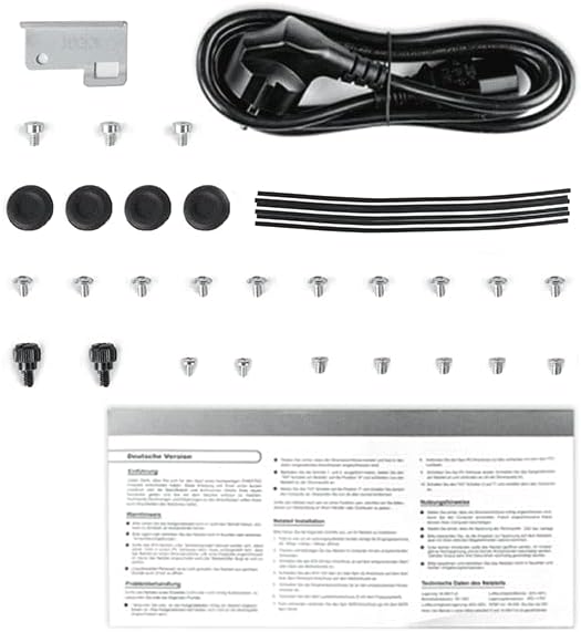
Figure 5.1: Drive bay configuration diagram, indicating mounting points for various storage devices.
- 5.25" Ultra-Slim ODD (9.5 mm): Slide the optical drive into the designated bay from the front and secure it with screws or the tool-less mechanism if available.
- HDD da 3.5" / SSD da 2.5": Mount the drives into the appropriate brackets or bays as shown in Figure 5.1. Secure them with screws.
5.6 Installazione della scheda di espansione
Remove the necessary expansion slot covers from the rear of the case. Insert your expansion card (e.g., graphics card, network card) into the motherboard's PCIe slot and secure it using the tool-less lock mechanism or a screw.
5.7 Gestione dei cavi
Route all cables (power, data, front panel) neatly to ensure optimal airflow and a clean build. Use cable ties from the accessory kit to bundle cables.
5.8 Chiusura del caso
Once all components are installed and cables are managed, carefully slide the side panel back into place and secure it with the thumbscrews or latches.
6. Istruzioni per l'uso
6.1 Accensione/Spegnimento
- Connect the power cord to the power supply unit and a wall outlet.
- Press the power button located on the front panel of the case to turn on your computer.
- To turn off, use the operating system's shutdown function or press and hold the power button for several seconds.
6.2 Collegamento delle periferiche
Connect your monitor, keyboard, mouse, and other peripherals to the appropriate ports on the rear I/O panel of your motherboard and the front I/O panel of the case.
7. Manutenzione
7.1 Pulizia
- Pulire regolarmente l'esterno della custodia con un panno morbido eamp stoffa. Evitare detergenti abrasivi.
- Periodically open the case and use compressed air to remove dust buildup from internal components, especially fans and heatsinks, to maintain optimal cooling performance.
8. Risoluzione Dei Problemi
In caso di problemi, fare riferimento ai seguenti passaggi comuni per la risoluzione dei problemi:
- Nessun potere: Ensure the power cord is securely connected to both the wall outlet and the power supply. Check the power switch on the power supply itself.
- Nessuna visualizzazione: Verify that your monitor is connected to the correct video output port on your graphics card or motherboard and that the monitor is powered on.
- Instabilità del sistema: Check all internal cable connections (power, data, motherboard headers) to ensure they are firmly seated. Verify that all components are properly installed.
- Surriscaldamento: Ensure all case fans are spinning and not obstructed. Clean any dust buildup from fans and heatsinks.
Per problemi più complessi, consultare i manuali dei componenti o rivolgersi a un professionista.
9. Specifiche
| Caratteristica | Specificazione |
|---|---|
| Numero di modello | BE-10B-300 |
| Marca | Capotecnico |
| Tipo di caso | Small Form Factor (SFF) Desktop |
| Colore | Nero |
| Materiale | Acciaio legato |
| Compatibilità della scheda madre | Mini ATX, Micro ATX |
| Alimentazione elettrica | 300W (incluso) |
| Tipo di montaggio dell'alimentatore | Montaggio inferiore |
| Metodo di raffreddamento | Aria |
| Dimensioni della ventola | 80 mm (8E+1 Millimeters) |
| Dimensioni del prodotto | 10 x 2 x 2.7 pollici |
| Peso dell'articolo | 8.84 libbre |
| Usi consigliati | Scopo generale |
10. Garanzia e supporto
10.1 Informazioni sulla garanzia
Chieftec products are manufactured to high-quality standards. For specific warranty terms and conditions, please refer to the warranty card included with your product or visit the official Chieftec websito. Conservare la prova d'acquisto per eventuali reclami in garanzia.
10.2 Supporto tecnico
If you encounter any issues that cannot be resolved using the troubleshooting guide in this manual, please contact Chieftec customer support or your retailer for assistance. Contact information can typically be found on the Chieftec websul sito o sulla confezione del prodotto.