
1. Introduzione
This manual provides essential information for the safe and efficient operation of your PowerWalker VFI 1000 AT FR Online Uninterruptible Power Supply (UPS). The VFI AT series utilizes double-conversion technology to provide reliable power protection for critical devices. Please read this manual thoroughly before installation and use, and retain it for future reference.
2. Istruzioni di sicurezza
WARNING: Failure to follow these safety instructions can result in fire, electric shock, serious injury, or death.
- Non aprire l'UPS casing. All'interno non sono presenti parti riparabili dall'utente. Per qualsiasi intervento di assistenza, rivolgersi a personale qualificato.
- Non collegare apparecchi che potrebbero sovraccaricare l'UPS, come asciugacapelli o aspirapolvere.
- Ensure the UPS is connected to a properly grounded power outlet.
- Do not block ventilation openings. Maintain adequate clearance around the UPS for proper airflow.
- Evitare di installare l'UPS in aree con polvere eccessiva, umidità o temperature estreme.
- In case of emergency, press the OFF button and disconnect the UPS from the AC power source.
3. Prodotto finitoview
The PowerWalker VFI 1000 AT FR UPS is designed to provide clean, stable power to your connected equipment. It features a user-friendly interface and various connectivity options.
3.1 Pannello frontale

Figure 3.1: Front Panel of the UPS. This image shows the main display screen indicating input and output voltage, battery status, and load level. Below the screen are four control buttons: ON, OFF, ENTER, and ESC.
The front panel includes an LCD display that provides real-time information about the UPS status, such as input/output voltage, battery charge, and load level. Control buttons allow for easy navigation and configuration.
- Schermo LCD: Mostra lo stato operativo e i parametri.
- Pulsante ON: Accende l'UPS.
- Pulsante SPENTO: Spegne l'UPS.
- Pulsante INVIO: Conferma le selezioni o accede ai menu.
- Pulsante ESC: Esce dai menu o annulla le operazioni.
3.2 Pannello posteriore
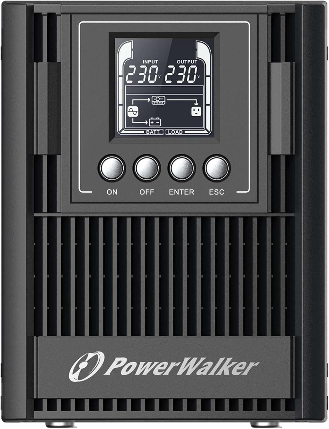
Figure 3.2: Rear Panel of the UPS. This image displays the connectivity options including a serial port (DB9), cooling fan, multiple Type F outlets, a USB port, an EPO (Emergency Power Off) terminal, and the AC input socket.
The rear panel provides all necessary connections for input power, output to protected devices, and communication interfaces.
- Ingresso CA: Collega l'UPS all'alimentazione principale.
- Prese di uscita: Type F, Type E, or Type G outlets (depending on model) for connecting protected equipment.
- Porta USB: For communication with a computer and monitoring software.
- RS-232 Port (Serial): For advanced communication and monitoring.
- Terminale EPO (spegnimento di emergenza): For remote emergency shutdown.
- Slot intelligente: Per schede di comunicazione opzionali (ad esempio, scheda SNMP).
- Connettore batteria esterna: For connecting optional external battery packs to extend backup time.
4. Impostazione
4.1 Disimballaggio e ispezione
Disimballare con cura l'UPS e ispezionarlo per verificare eventuali danni causati dal trasporto. In caso di danni, non installare l'unità e contattare il rivenditore.
4.2 Posizionamento
Place the UPS in a clean, dry, and well-ventilated area. Ensure sufficient clearance (at least 20 cm) around the unit for proper heat dissipation. Avoid direct sunlight, heat sources, and excessive moisture.
4.3 Carica iniziale
Before initial use, connect the UPS to a standard AC power outlet for at least 8 hours to ensure the internal batteries are fully charged. The UPS will charge its batteries whether it is turned ON or OFF.
4.4 Apparecchiatura di collegamento
- Connect your critical equipment (computers, monitors, network devices) to the output sockets on the rear panel of the UPS.
- Connect the UPS power cord to a grounded AC power outlet.
- (Optional) Connect the USB or RS-232 cable from the UPS to your computer for monitoring and management.
- (Optional) If using external battery packs, connect them according to their specific instructions to the designated connector on the UPS.
5. Funzionamento dell'UPS
5.1 Accensione dell'UPS
Premere e tenere premuto il tasto ON button on the front panel for approximately 2 seconds until you hear a beep and the LCD display illuminates. The UPS will perform a self-test and then enter normal operating mode.
5.2 Spegnimento dell'UPS
To turn off the UPS, press and hold the SPENTO button for approximately 2 seconds until the LCD display turns off. Ensure all connected equipment is properly shut down before turning off the UPS.
5.3 Display LCD e navigazione
The LCD display provides various operational parameters. Use the ENTRARE E ESC buttons to navigate through menus and view different information screens. The display automatically darkens after a period of inactivity and can be woken up with a single button press.
5.4 Remote Shutdown (RPO)
The UPS supports Remote Power Off (RPO) functionality. Connect an external switch to the EPO terminal on the rear panel. Activating this switch will immediately shut down the UPS and connected equipment. Refer to the wiring diagram in the advanced user manual for proper connection.
6. Manutenzione
6.1 Cura della batteria
The UPS contains internal lithium batteries. To maximize battery life:
- Keep the UPS connected to AC power to keep batteries charged.
- Evitare di conservare l'UPS a temperature estreme.
- Perform a battery calibration (if available via software) or a full discharge/recharge cycle every 3-6 months.
- Replace batteries when their capacity significantly degrades. Battery replacement should only be performed by qualified personnel.
6.2 Pulizia
Pulire l'esterno dell'UPS con un panno morbido e asciutto. Non utilizzare detergenti liquidi o spray. Assicurarsi che le aperture di ventilazione siano libere da polvere e detriti.
6.3 Conservazione
If storing the UPS for an extended period, ensure the batteries are fully charged. Recharge the batteries every three months to prevent permanent damage.
7. Risoluzione Dei Problemi
Questa sezione fornisce soluzioni ai problemi più comuni che potresti riscontrare con il tuo UPS. Se il problema persiste, contatta l'assistenza tecnica.
| Problema | Possibile causa | Soluzione |
|---|---|---|
| L'UPS non si accende. | No AC input power; Low battery charge. | Check AC power connection; Allow UPS to charge for 8 hours. |
| L'UPS emette segnali acustici continui. | Sovraccarico; Batteria scarica; Condizione di guasto. | Reduce connected load; Allow batteries to charge; Check LCD for error codes. |
| Tempo di backup breve. | Batterie non completamente cariche; Batterie prossime alla fine del ciclo di vita. | Ensure full charge; Consider battery replacement. |
| Connected equipment not receiving power. | UPS is off; Output sockets not enabled; UPS in fault mode. | Turn on UPS; Check LCD for status; Consult manual for output settings. |
8. Specifiche
| Caratteristica | Dettaglio |
|---|---|
| Modello | VFI 1000 AT FR (Model Number: 10122183) |
| Marca | PowerWalker |
| Capacità di potenza in uscita | 900W |
| Ingresso volumetage | 220V (Wide input voltage gamma) |
| Tipo di batteria | Litio |
| Prese di uscita | Type F, Type E, Type G (various versions available) |
| Porte di comunicazione | USB (HID support), RS-232, Intelligent Slot |
| Dimensioni (A x L x P) | 50 x 10 x 48 cm (circa) |
| Peso | 2 chilogrammi |
| Caratteristiche speciali | Double-conversion online technology, Generator compatible, RPO, External battery pack support, Automatically darkening LCD. |
9. Garanzia e supporto
The PowerWalker VFI 1000 AT FR UPS is covered by a standard manufacturer's warranty. Please refer to the warranty card included with your product or visit the official PowerWalker websito per termini e condizioni di garanzia dettagliati.
For technical support, troubleshooting assistance beyond this manual, or spare parts inquiries, please contact your local dealer or PowerWalker customer service. The EU Spare Part Availability Duration is 2 Years.