
1. Introduzione
The VDIAGTOOL V200 Automotive Circuit Tester is a versatile diagnostic tool designed for electrical system testing in 12V-24V vehicles. It combines multiple functions to assist in identifying and troubleshooting electrical faults efficiently.

Figure 1: VDIAGTOOL V200 Automotive Circuit Tester and included accessories.
2. Cosa c'è nella scatola
- Tester per sonde di circuito
- Extension Cable (20 ft)
- Adattatore per accendisigari
- Manuale d'uso
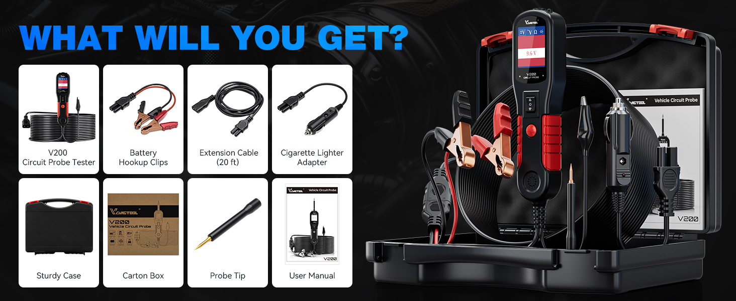
Figure 2: All components included in the VDIAGTOOL V200 kit.
3. Impostazione
The V200 is powered by the vehicle's 12V-24V battery. Connect the red alligator clip to the positive (+) terminal and the black alligator clip to the negative (-) terminal of the vehicle battery. Alternatively, use the provided cigarette lighter adapter for power.
3.1 Alimentazione del dispositivo
- Collegamento della batteria: Attacca il cl rossoamp al polo positivo della batteria e il nero clamp al polo negativo della batteria.
- Collegamento accendisigari: Insert the cigarette lighter adapter into the vehicle's 12V accessory socket.
Video 1: Demonstrates the unboxing and initial setup of the VDIAGTOOL V200, including connecting to a car battery.
4. Modalità operative
The V200 supports four primary working modes, easily switchable with a single button press.
- Volume DCtage Prova: Detects the DC voltage value of the circuit under test with 0.1V resolution.
- Volume ACtage Prova: Detects Max/Min voltage, frequency, and duty cycle of the AC circuit.
- Prova di resistenza: Misura la resistenza tra la punta della sonda e il cavo di terra ausiliario.
- Prova del diodo: Determines the operation and conductivity of diode assemblies.

Figure 3: The V200 display interface illustrating the four main working modes.
5. Funzioni chiave
5.1 Polarity Identification
The V200 automatically identifies circuit polarity. A red LED indicates a positive connection, while a green LED indicates a negative connection. No LED indicates an open circuit.

Figure 4: Visual representation of polarity identification using the V200's LED indicators.
5.2 Attivazione dei componenti
This feature allows you to activate components (e.g., lights, motors, relays) by supplying power or ground directly from the probe, aiding in troubleshooting. Use caution to avoid damaging components by applying incorrect polarity or excessive current.

Figure 5: Illustration of component activation for testing a car bulb.
5.3 Continuity, Sensor/Signal Circuit Test
Perform continuity tests, check sensor states, and verify signal integrity within circuits. The tool can also help locate short circuits and bad grounds.
6. Caratteristiche di sicurezza
6.1 Protezione da sovraccarico
The V200 features a built-in 8-amp circuit breaker. In case of an overload, the device will automatically shut down to protect itself and the tested components. A beep warning will also occur.

Figure 6: Visual indicator of the overload protection feature.
7. Specifiche
- Dimensioni del prodotto: 1.85 x 1.1 x 7 pollici
- Peso dell'articolo: 1.17 chilogrammi (2.58 libbre)
- Fonte di energia: Corded Electric (12V-24V vehicle battery or cigarette lighter)
- Numero modello: VDT-V200-P
- Lunghezza del cavo: 20FT main cord + 20FT extension cord (Total 40FT)
- Caratteristiche aggiuntive: Built-in flashlight, Tone On/Off Design
8. Manutenzione
To ensure the longevity and optimal performance of your VDIAGTOOL V200, follow these general maintenance guidelines:
- Keep the device clean and free from dust, dirt, and moisture.
- Store the tester and its accessories in the provided sturdy case when not in use.
- Inspect cables and connectors regularly for any signs of wear or damage. Replace if necessary.
- Evitare di esporre il dispositivo a temperature estreme o alla luce solare diretta per periodi prolungati.
9. Risoluzione Dei Problemi
If you encounter issues with your VDIAGTOOL V200, consider the following:
- Il dispositivo non si accende: Ensure secure connections to the vehicle's battery or cigarette lighter. Verify the vehicle's power source is active.
- Nessuna lettura/lettura errata: Check that the probe tip is making good contact with the circuit. Ensure the correct operating mode is selected.
- Protezione da sovraccarico attivata: If the device shuts down with a beep, it indicates an overload. Disconnect the probe, allow a few moments, and then reconnect. Reduce the load or verify the circuit's specifications before retesting.
- Problemi di schermo: If the screen is blank or unresponsive, try disconnecting and reconnecting the power source.
10. Garanzia e supporto
VDIAGTOOL offers comprehensive support for the V200 Automotive Circuit Tester:
- Garanzia: Garanzia di 3 anni.
- Assistenza tecnica: Assistenza tecnica a vita.
- Resi: 60 Days No-Reason-asked Return for refund.
- Sostituzione della sonda: Free probe replacement.
- Contatta l'assistenza: For any questions or assistance, kindly reach us via vdiagtool2@outlook.com.