1. Introduzione
The Generic UT501A Insulation Resistance Tester is a digital megger designed for measuring insulation resistance in various electrical equipment and household appliances. This device is part of the UT500 series, capable of measuring insulation resistance, AC voltage, low resistance, Polarization Index (PI), and Dielectric Absorption Ratio (DAR). It is an essential tool for ensuring the safe and accurate operation of transformers, generators, high-voltage motors, power capacitors, power cables, arresters, and other electrical systems.
Key features include a 2000-count LCD display, an overload indicator, AC voltage measurement with backlight, automatic power-off, continuous measurement mode, a red warning light, and a buzzer function for enhanced safety and usability.
2. Informazioni sulla sicurezza
AVVERTIMENTO: To avoid electric shock or personal injury, please read all safety information before using this product. Use the product only as specified in this manual, or the protection provided by the product may be impaired.
- Always inspect the tester, test leads, and accessories for damage before each use. Do not use if damaged.
- Non applicare più del volume nominaletage, come indicato sul tester, tra i terminali o tra un terminale qualsiasi e la terra.
- Usare cautela con voltagsuperiori a 30 V CA RMS, 42 V di picco o 60 V CC. Tale voltagrappresentano un rischio di scossa elettrica.
- Scollegare i puntali di prova dal circuito sottoposto a test prima di modificare le funzioni o gli intervalli.
- Prima dell'uso, assicurarsi che il vano batteria sia ben chiuso.
- Do not operate the tester in explosive gas, vapor, or dusty environments.
- Always discharge the circuit under test after insulation resistance measurements. The UT501A features automatic discharge.
- Rispettare i codici di sicurezza locali e nazionali.
3. Contenuto della confezione
Verify that all items listed below are present and in good condition. If any item is missing or damaged, contact your supplier.
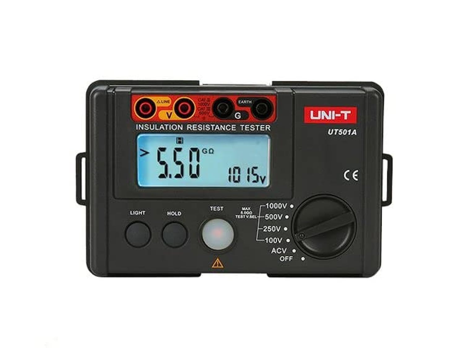
Image: The Generic UT501A Insulation Resistance Tester, including the main unit, test leads, carrying case, and user manual.
- UT501A Insulation Resistance Tester Unit
- Cavi di prova (rosso e nero)
- Clip a coccodrillo
- Custodia per il trasporto
- Manuale d'uso
- Tracolla
4. Prodotto finitoview
The UT501A features a robust design suitable for field use. Its intuitive interface allows for easy selection of measurement functions and clear display of results.
4.1 Pannello frontale
- Schermo LCD: Display da 2000 con retroilluminazione per letture chiare in diverse condizioni di illuminazione.
- Funzione Interruttore Rotativo: Used to select measurement modes (Insulation Resistance, AC Voltage, Low Resistance, etc.).
- Pulsanti di prova: Initiate and stop measurements.
- Terminali di ingresso: Connect test leads for various measurements.
- Indicatore di sovraccarico: Visual alert for measurement range exceeding limits.
- Spia luminosa: Red light indicates high voltage output during insulation tests.
5. Impostazione
5.1 Installazione della batteria
The UT501A is powered by batteries (type and quantity typically specified in the full manual, assume standard AA or AAA for general instruction). To install or replace batteries:
- Ensure the tester is powered off and disconnect all test leads.
- Individuare il coperchio del vano batterie sul retro dell'unità.
- Svitare o sbloccare il coperchio e rimuoverlo.
- Inserire le batterie nuove, rispettando la polarità corretta (+ e -).
- Riposizionare il coperchio del vano batteria e fissarlo.
5.2 Collegamento dei puntali di prova
Connect the test leads to the appropriate input terminals on the tester. For insulation resistance measurements, typically the red lead connects to the 'LINE' or 'VΩ' terminal and the black lead to the 'EARTH' or 'COM' terminal. Refer to the markings on the device for specific connections for different functions.
6. Istruzioni per l'uso
Before any measurement, ensure the circuit under test is de-energized and safely isolated, unless performing AC voltage misurazioni.
6.1 Misurazione della resistenza di isolamento
- Turn the rotary switch to the desired insulation resistance test voltage (ad esempio, 100 V, 250 V, 500 V, 1000 V).
- Connect the test leads to the circuit or component to be tested. Ensure proper contact.
- Press and hold the 'TEST' button. The red warning light will illuminate, indicating high voltage uscita.
- Read the insulation resistance value on the LCD display.
- Rilasciare il pulsante 'TEST' per interrompere la misurazione. Il circuito si scaricherà automaticamente.
6.2 Volume ACtage Misurazione
- Turn the rotary switch to the 'ACV' position.
- Collegare i puntali di prova ai punti in cui la tensione CAtage deve essere misurato.
- Il volume ACtagIl valore verrà visualizzato sul display LCD.
6.3 Misurazione della bassa resistenza
- Turn the rotary switch to the 'Ω' (Ohms) position.
- Connect the test leads to the component or circuit for low resistance measurement.
- Leggere il valore della resistenza sul display LCD.
6.4 Indice di polarizzazione (PI) e rapporto di assorbimento dielettrico (DAR)
The UT501A can calculate PI and DAR, which are important indicators of insulation quality. These measurements typically involve taking insulation resistance readings at specific time intervals (e.g., 1 minute and 10 minutes for PI, 30 seconds and 60 seconds for DAR) and the meter automatically calculates the ratio. Refer to the detailed instructions in the full manual for specific steps on activating and interpreting these functions.
7. Manutenzione
7.1 Pulizia
Pulisci la custodia con l'adamp panno e detergente delicato. Non utilizzare abrasivi o solventi. Assicurarsi che il dispositivo sia completamente asciutto prima dell'uso.
7.2 Conservazione
When not in use for extended periods, remove the batteries to prevent leakage. Store the tester and accessories in the provided carrying case in a cool, dry place, away from direct sunlight and extreme temperatures.
8. Risoluzione Dei Problemi
- Nessun display/alimentazione: Controllare l'installazione della batteria e il livello di carica. Sostituire le batterie se necessario.
- Letture imprecise: Ensure test leads are properly connected and not damaged. Verify the correct function and range are selected. Clean test points.
- Indicatore di sovraccarico: The measured value exceeds the selected range. Select a higher range or verify the circuit conditions.
- Buzzer/Warning Light Active: Ciò indica un alto volumetage output during insulation tests. This is normal during a test. If it persists after releasing the TEST button, ensure the circuit has discharged.
9. Specifiche
| Caratteristica | Specificazione |
|---|---|
| Marca | Generico |
| Modello | UT501A |
| Fonte di alimentazione | Elettrico con filo (Note: This likely refers to the test leads, the device itself is battery-powered) |
| Colore | Rosso |
| Tipo di misurazione | Insulation Resistance, AC Voltage, Low Resistance, PI, DAR |
| Massimo volume di eserciziotage | 1000 Volt |
| Display | 2000-count LCD with backlight |
| Spegnimento automatico | SÌ |
| Scarico automatico | SÌ |
| Paese di origine | Cina |
10. Garanzia
This product is sold without a manufacturer's warranty. Please refer to your retailer's return policy for any issues upon purchase.
11. Supporto
For further assistance or inquiries regarding the Generic UT501A Insulation Resistance Tester, please contact your point of purchase or the manufacturer's customer support channels if available. Always refer to the complete user manual provided with your device for the most detailed and up-to-date information.