1. Introduzione
This manual provides detailed instructions for the proper setup, operation, and maintenance of your HOTRC CT-4A 4-channel 2.4GHz RC Transmitter and Receiver system. Designed for use with RC cars, boats, and tanks, this system offers stable control and advanced features. Please read this manual thoroughly before use to ensure safe and optimal performance.
2. Cosa c'è nella scatola
- 1 x CT-400 Remote Controller
- 1 x CT-600 4+2channel Receiver
- 1 x Manuale utente
3. Prodotto finitoview
The HOTRC CT-4A transmitter features an ergonomic pistol-grip design for comfortable one-handed operation. The control panel includes various buttons and trims for precise adjustments.

Figura 3.1: HOTRC CT-4A Transmitter with labeled components including antenna, operation panel, handwheel, trigger, and battery compartment.
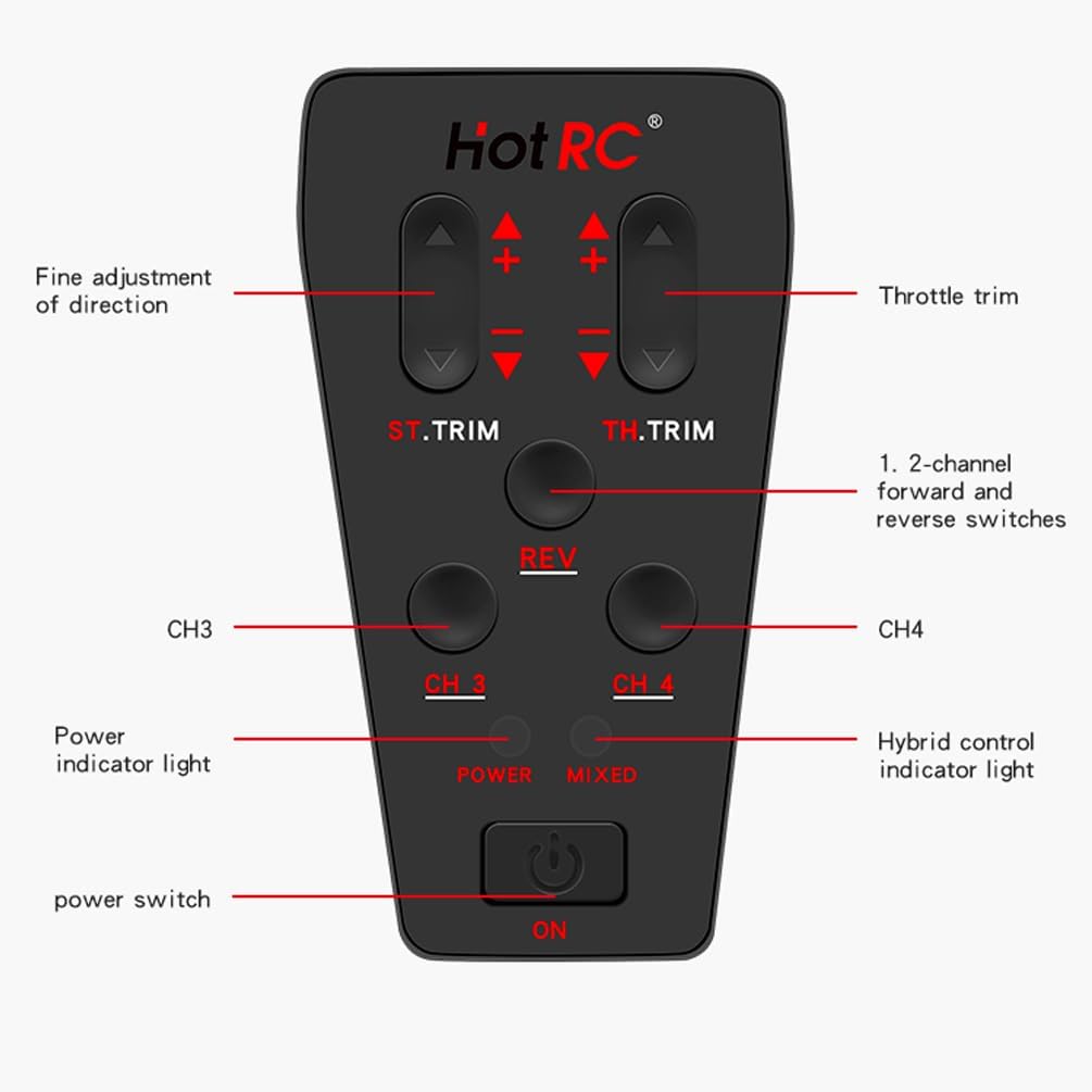
Figura 3.2: Dettagliato view of the CT-4A control panel, showing ST.TRIM, TH.TRIM, REV, CH3, CH4 buttons, Power indicator, Mixed control indicator, and Power switch.
4. Impostazione
4.1 Installazione della batteria
The transmitter supports two power supply methods: 2S lithium batteries or 4 AA batteries. The innovative detachable battery box allows direct insertion of a 2S lithium battery balance port.
- Aprire il coperchio del vano batterie situato nella parte inferiore del trasmettitore.
- Insert 4 AA batteries, observing correct polarity, or connect a 2S lithium battery to the designated port.
- Chiudere saldamente il coperchio del vano batterie.
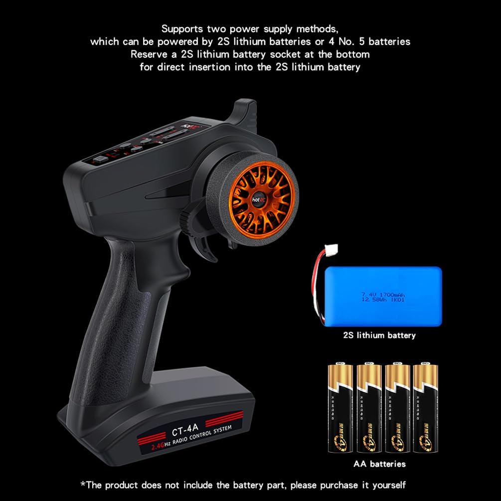
Figura 4.1: Illustration of battery installation options for the CT-4A transmitter, showing both 2S lithium battery and AA battery configurations.
4.2 Collegamento del ricevitore
The receiver supports a voltage supply of 4-9V and both numerical and analog servo modes. Connect your servos and other components to the appropriate channels on the receiver.
- Connect the receiver to your RC vehicle's components (servos, ESC, etc.).
- Ensure all connections are secure and correctly oriented.
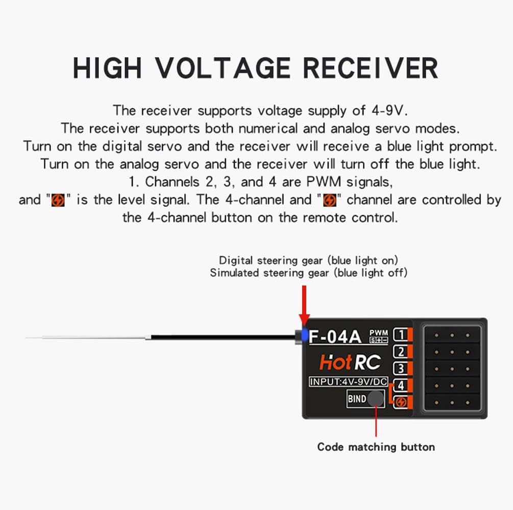
Figura 4.2: The CT-600 receiver showing the bind button and channel ports. Channels 2, 3, and 4 are PWM signals. The 4-channel and 'CH1' channel are controlled by the 4-channel button on the remote control.
4.3 Processo di rilegatura
To establish communication between the transmitter and receiver, follow these steps:
- Assicurarsi che il trasmettitore sia spento.
- Insert the bind plug (codec) into the receiver's BIND/CH5 port.
- Power on the receiver. The LED on the receiver should start flashing.
- Press and hold the 'BIND' button on the transmitter while powering it on.
- Release the 'BIND' button once the transmitter powers on. The LED on the receiver should become solid, indicating successful binding.
- Power off both the transmitter and receiver. Remove the bind plug from the receiver.
- Power on the transmitter first, then the receiver. The system should now be bound and ready for operation.
5. Istruzioni per l'uso
5.1 Controlli di base
The CT-4A features an ergonomic pistol-grip and steering wheel for intuitive control. The throttle speed limit can be adjusted, and it includes brake and fail-safe functions.
5.2 Positive and Negative Channel Settings
This setting allows you to reverse the direction of specific channels if needed for your model.
5.1 video: Instructions for setting positive and negative channels on the HOTRC CT-4A transmitter. This video demonstrates how to adjust channel direction by holding the REV key and manipulating the CH1 handwheel or CH2 trigger. A sound indicates successful setting.
5.3 Stroke Amount Adjustment
Adjusting the stroke amount allows you to fine-tune the range of movement for your servos.
5.2 video: Guide on setting the stroke amount for the HOTRC CT-4A. This video shows how to enter adjustment mode by powering on the transmitter while holding the REV key, then using the trim buttons to adjust CH1 and CH2 stroke. The stroke is divided into 5 levels, with the default being the largest.
5.4 Mixing Control Setting
The CT-4A allows for mixed control mode on channels 1-2. This feature can be useful for specific vehicle configurations.
5.3 video: Demonstration of how to activate mixing control on the HOTRC CT-4A. To enable, press and hold the CH3 and CH4 switches simultaneously while powering on the remote control. The mixing indicator light on the panel will illuminate, confirming successful activation. The same method is used to disable it.
5.5 Out of Control Protection (Fail-Safe) Setting
The fail-safe function protects your model by setting predefined servo positions in case of signal loss, preventing loss of control.
5.4 video: Instructions for setting the out-of-control protection (fail-safe) function. First, ensure the code is successfully matched. Then, control the transmitter's throttle channel to the desired braking or stalling state. Insert the encoder into the receiver's bind pairing hole. The LED light will flash, then remain solid when the fail-safe is set. Test by turning off the transmitter power and observing if the throttle servo moves to the set position.
6. Specifiche
| Specificazione | Valore |
|---|---|
| Tipo di modello | Auto, barca, carro armato |
| Canali | 4 canale |
| Gamma RF | 2.4Ghz ISM (2.4005 - 2.483.5Ghz) |
| Potenza RF | <100mW |
| Modulazione | GFSK |
| Spread Spectrum | FHSS |
| Velocità di reazione | PWM≤20ms |
| Distanza RF (terra) | 400m-500m |
| Ricevi sensibilità | <-97dbm |
| Volume trasmettitoretage | DC 4.5-9V |
| Ricevitore voltage | CC 4V-14V |
| Peso lordo | 196g |
| Dimensioni del pacco | 8.98 x 6.42 x 3.98 pollici |
| Peso dell'articolo | 8 once |
7. Manutenzione
To ensure the longevity and reliable performance of your HOTRC CT-4A system, follow these maintenance guidelines:
- Pulizia: Utilizzare un panno morbido e asciutto per pulire il trasmettitore e il ricevitore. Evitare l'uso di prodotti chimici o solventi aggressivi.
- Magazzinaggio: Conservare il sistema in un luogo fresco e asciutto, lontano dalla luce solare diretta e da temperature estreme. Rimuovere le batterie dal trasmettitore in caso di conservazione per periodi prolungati per evitare perdite.
- Ispezione: Periodically check all cables and connectors for signs of wear or damage. Ensure the antenna is not bent or broken.
- Cura della batteria: Always use recommended batteries and follow proper charging procedures for rechargeable types.
8. Risoluzione Dei Problemi
If you encounter issues with your HOTRC CT-4A system, refer to the following common troubleshooting steps:
- Nessun potere: Check battery installation and ensure batteries are fully charged or new. Verify the power switch is in the 'ON' position.
- Nessun problema di segnale/associazione: Re-perform the binding process as described in Section 4.3. Ensure the receiver is powered correctly and within range of the transmitter. Check for any interference from other 2.4GHz devices.
- Movimento irregolare del servo: Check all servo connections to the receiver. Ensure the receiver is receiving adequate power. Verify that the channel settings (positive/negative, stroke amount) are correctly configured.
- Gamma limitata: Ensure the transmitter and receiver antennas are not obstructed or damaged. Avoid operating in areas with high radio interference.
- I controlli non rispondono: Confirm the system is properly bound. Check if the fail-safe function has been triggered due to signal loss.
9. Garanzia e supporto
For warranty information or technical support, please refer to the contact details provided with your product packaging or visit the official HOTRC websito. Conservare la ricevuta d'acquisto come prova d'acquisto per eventuali reclami in garanzia.