
1. Introduzione
The Ortis Hi-Lo Sump Pump Switch Controller KJ-033 is an electronic adjustable float switch designed for automatic water level management in various applications such as sewage pits, fish tanks, and water tanks. It features stainless steel anti-corrosion dual sensors and supports both 220V and 110V AC power inputs. This manual provides detailed instructions for installation, operation, maintenance, and troubleshooting to ensure optimal performance and longevity of your device.
2. Informazioni sulla sicurezza
Leggere attentamente tutte le istruzioni di sicurezza prima dell'installazione e dell'uso. La mancata osservanza di queste istruzioni può causare scosse elettriche, incendi o lesioni gravi.
- Rischio elettrico: Assicurarsi che l'alimentazione sia scollegata prima di eseguire qualsiasi installazione, manutenzione o risoluzione dei problemi.
- Voltage Compatibilità: Verificare che l'alimentazione vol.tage matches the controller's specifications (220V/110V AC).
- Messa a terra corretta: Always connect the device to a properly grounded outlet.
- Esposizione all'acqua: Do not immerse the controller unit in water. The controller unit is designed to be mounted above the water level.
- Personale qualificato: Installation and electrical connections should be performed by qualified personnel if you are unsure.
- Condizioni ambientali: Do not operate the device in explosive atmospheres or where flammable liquids or gases are present.
3. Caratteristiche del prodotto
The Ortis KJ-033 controller offers several features for reliable water level management:
- Dual Stainless Steel Sensors: Anti-corrosion sensors for accurate water level detection.
- Adjustable Sensor Range: Sensors can be adjusted from 1/2 inch to 20 inches to define high and low water levels.
- Molteplici modalità operative: Supports Drain Mode (for emptying) and Water Mode (for filling).
- Indicatori LED: Visual feedback for power, load status, and alarm conditions.
- Protezione da sovraccarico: Integrated protection for connected pumps.
- Funzione muto: Allows silencing of the alarm.
- Ampia applicazione: Suitable for sewage pits, fish tanks, water tanks, and other water management systems.
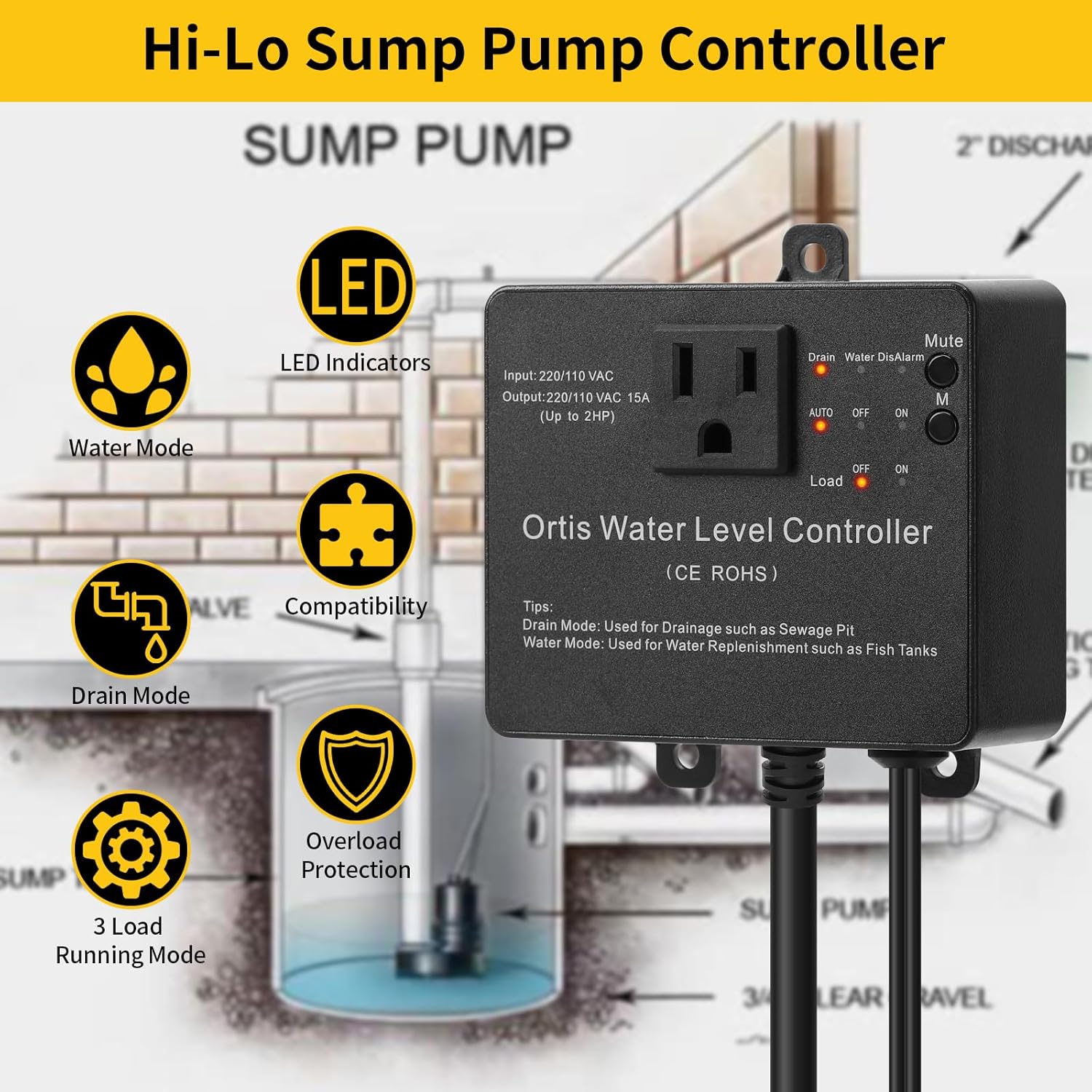
Figura 3.1: Ortis Water Level Controller Overview con caratteristiche principali.
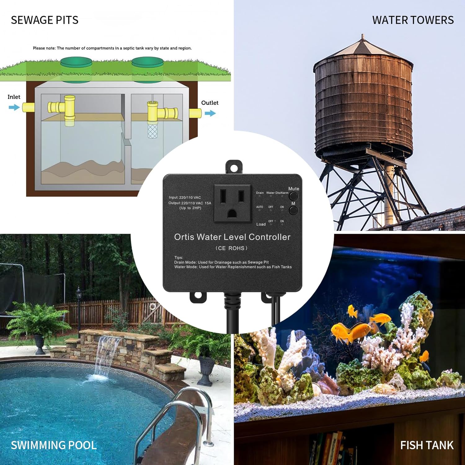
Figura 3.2: Various Application Scenarios for the Controller.
4. Configurazione e installazione
Proper installation is crucial for the reliable operation of the controller.
4.1 Montaggio del controller
The controller unit should be mounted in a dry location, above the maximum water level, and within reach of a grounded power outlet.
- Montaggio a vite: Use appropriate screws and anchors to secure the controller to a wall or stable surface through the mounting tabs.
- Montaggio a ventosa: For temporary or non-permanent installations, a suction cup can be used to attach the controller to a smooth, clean surface.

Figura 4.1: Controller Installation Methods.
4.2 Sensor Installation and Adjustment
The dual sensors detect the high and low water levels. Their position determines the operating range of your pump.
- Posizionamento del sensore: Position the sensors vertically in the water, ensuring they are securely fastened and will not move. The lower sensor defines the 'low' water level, and the upper sensor defines the 'high' water level.
- Intervallo regolabile: The sensors can be adjusted along their cables to set the desired water level range, from 1/2 inch to 20 inches apart. Ensure both sensors are submerged at the desired 'on' level and the lower sensor is exposed at the desired 'off' level for drain mode, or vice versa for water mode.
- Gestione dei cavi: Route sensor cables to prevent entanglement or damage.

Figura 4.2: Adjustable Sensor Installation.
4.3 Collegamento elettrico
- Spina di alimentazione: Plug the controller's power cord into a grounded 220V or 110V AC outlet.
- Collegamento della pompa: Plug your sump pump or other load device into the outlet on the front of the controller. Ensure the pump's power requirements do not exceed the controller's output capacity (15A, up to 2HP).

Figura 4.3: Example Sump Pit Installation.
5. Istruzioni per l'uso
The controller features a simple interface for selecting operating modes and managing alarms.

Figura 5.1: Pannello di controllo Fineview.
5.1 Selezione della modalità
Use the 'Drain' and 'Water' buttons to select the desired operating mode:
- Modalità di scarico: (LED indicator 'Drain' illuminates) In this mode, the controller activates the pump when the water level reaches the upper (high) sensor and deactivates it when the water level drops below the lower (low) sensor. This mode is typically used for emptying sewage pits or sumps.
- Modalità acqua: (LED indicator 'Water' illuminates) In this mode, the controller activates the pump when the water level drops below the lower (low) sensor and deactivates it when the water level reaches the upper (high) sensor. This mode is typically used for replenishing water in fish tanks or water tanks.
5.2 Power and Operation Switch
The main switch controls the power and operational state of the connected load:
- AUTO: (LED indicator 'AUTO' illuminates) The controller operates automatically based on the selected mode (Drain or Water) and sensor readings.
- OFF: (LED indicator 'OFF' illuminates) The connected pump is turned off, regardless of water levels.
- SOPRA: (LED indicator 'ON' illuminates) The connected pump is continuously turned on, regardless of water levels. Use this for manual override or continuous operation.
5.3 Funzione Mute
Press the 'Mute' button to silence any active alarms. The 'DisAlarm' LED will illuminate when the alarm is muted.

Figura 5.2: Operational Logic in Drain Mode (Sewage Pit Example).
6. Manutenzione
Regular maintenance ensures the longevity and reliable operation of your Ortis controller.
- Pulizia del sensore: Periodically inspect and clean the stainless steel sensors to remove any buildup of debris, algae, or mineral deposits that could affect their accuracy. Disconnect power before cleaning.
- Ispezione dei cavi: Check all cables and connections for signs of wear, damage, or corrosion. Replace any damaged components immediately.
- Unità di controllo: Keep the controller unit clean and dry. Avoid exposing it to direct sunlight or extreme temperatures.
- Operazione di prova: Periodically test the controller's operation by manually raising or lowering water levels to ensure the pump activates and deactivates as expected in the selected mode.
7. Risoluzione Dei Problemi
Per i problemi più comuni e le relative soluzioni, fare riferimento alla tabella sottostante.
| Problema | Possibile causa | Soluzione |
|---|---|---|
| Pump does not turn on/off automatically. | 1. Controller not in AUTO mode. 2. Sensors are dirty or improperly positioned. 3. Pump is not plugged in or is faulty. | 1. Ensure the switch is set to 'AUTO'. 2. Clean sensors and verify their high/low positions. 3. Check pump connection and functionality. |
| L'allarme suona frequentemente. | 1. Water level not reaching desired sensor within expected time. 2. Malfunzionamento del sensore. 3. Alarm sensitivity setting (if applicable, check product documentation). | 1. Check pump operation and water flow. Adjust sensor positions if needed. 2. Inspect sensors for damage or debris. Replace if faulty. 3. Use the 'Mute' button temporarily. Consult manufacturer for alarm logic details. |
| Il controller non è alimentato. | 1. Cavo di alimentazione scollegato. 2. La presa non ha alimentazione. 3. Fusibile interno bruciato. | 1. Ensure power cord is securely plugged in. 2. Test the outlet with another device. Check circuit breaker. 3. Contatta l'assistenza clienti per assistenza. |
| Pump runs continuously in AUTO mode. | 1. Sensor stuck in 'on' position (e.g., upper sensor always wet in Drain Mode). 2. Controller malfunction. | 1. Clean and reposition sensors. Ensure they can freely detect water level changes. 2. Disconnect power and reconnect. If issue persists, contact support. |
8. Specifiche

Figura 8.1: Controller Dimensions.
| Caratteristica | Specificazione |
|---|---|
| Modello | Modello KJ-033 |
| Marca | Orti |
| Ingresso volumetage | 220V / 110V CA |
| Corrente di uscita | 15A |
| Potenza di carico massima | Fino a 2 CV |
| Materiale del sensore | Acciaio inossidabile |
| Gamma di sensori regolabile | Da 1/2 di pollice a 20 pollici |
| Produttore | FJKJ INC. |
9. Garanzia e supporto
For warranty information and technical support, please refer to the product packaging or contact the seller/manufacturer directly. Keep your purchase receipt as proof of purchase.
Produttore: FJKJ INC.