
1. Introduzione
This manual provides comprehensive instructions for the safe and efficient operation, setup, and maintenance of the GBHJJ IR6500 BGA Infrared Rework Station. This equipment is designed for precise soldering, desoldering, and repair of various packaged devices, including BGA, PBGA, CSP, multi-layer substrates, EMI metal shielding products, and lead-free re-soldering applications.
Caratteristiche principali:
- Controllo avanzato della temperatura: Features 8 heating sections and 8 constant temperature sections, allowing for precise control. Up to 10 sets of temperature curves can be saved.
- Innovative Airflow Management: Designed to minimize the impact of airflow on temperature accuracy, facilitating lead-free soldering rework.
- Secure PCB Fixture: Equipped with a linear rail-type bracket and special-shaped rod for easy and secure locking and adjustment, preventing PCB deformation.
- Progettazione integrata: Compact and integrated system design reduces workbench area requirements and cable clutter.
- Wide Application Scope: Suitable for BGA rework on various motherboards, including laptops, desktops, servers, industrial computers, game consoles, communication equipment, and LCD TVs.
2. Informazioni sulla sicurezza
ATTENZIONE: la mancata osservanza di queste istruzioni di sicurezza può causare scosse elettriche, incendi o lesioni gravi.
- Always connect the rework station to a grounded power outlet with the correct voltage (220 V).
- Do not operate the equipment in damp o in condizioni di bagnato.
- Ensure adequate ventilation in the work area to dissipate fumes and heat.
- The heating elements reach high temperatures. Avoid direct contact with hot surfaces. Use appropriate heat-resistant gloves.
- Scollegare l'alimentazione prima di effettuare qualsiasi operazione di manutenzione o pulizia.
- Keep children and unauthorized personnel away from the operating equipment.
- Do not modify the equipment. Use only manufacturer-approved replacement parts.
- Indossare sempre dispositivi di protezione individuale (DPI) adeguati, compresi gli occhiali di sicurezza.
3. Contenuto della confezione
Verifica che tutti gli articoli elencati di seguito siano presenti nel pacco. Se alcuni articoli risultano mancanti o danneggiati, contatta immediatamente il fornitore.

Immagine 3.1: Sopraview of the GBHJJ IR6500 BGA Infrared Rework Station and included accessories. This image displays the main rework station unit, power cable, USB cable, aluminum foil tape, and a thermocouple.
- GBHJJ IR6500 BGA Infrared Rework Station Unit
- Power Cable (AC220V compatible)
- Cavo USB
- Nastro del di alluminio
- Termocoppia
- Manuale dell'utente (questo documento)
4. Istruzioni per l'installazione
- Disimballaggio e posizionamento:
Carefully remove all components from the packaging. Place the rework station on a stable, level, and heat-resistant workbench. Ensure there is sufficient space around the unit for ventilation and operation.
- Collegamento elettrico:
Connect the provided power cable to the AC220V power inlet on the rear of the rework station. Ensure the power switch (circuit breaker) is in the OFF position before plugging the other end into a grounded 220V power outlet.
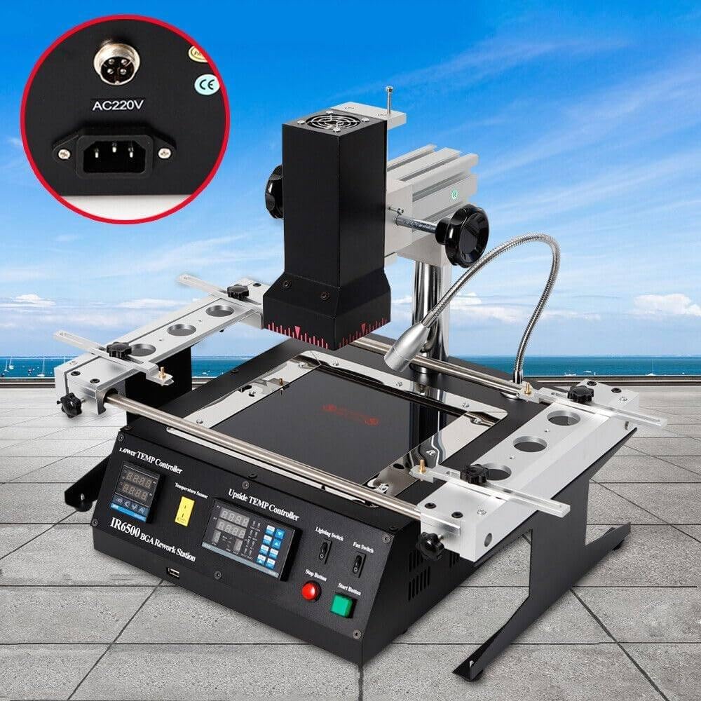
Immagine 4.1: Rear panel of the IR6500, highlighting the AC220V power input connector and the CE marking.

Immagine 4.2: Un altro view of the rear panel, showing the cooling fan on the left and the power input with an integrated circuit breaker on the right.

Immagine 4.3: Dettagliato view of the integrated circuit breaker, labeled "ADVANCON LZ47-63", which serves as the main power switch for the unit.
- PCB Board Mounting:
Utilize the linear rail-type bracket system to securely hold the PCB board. Adjust the special-shaped rod and rotate the handles to lock the PCB in place, ensuring it is stable and flat to prevent deformation during the rework process.
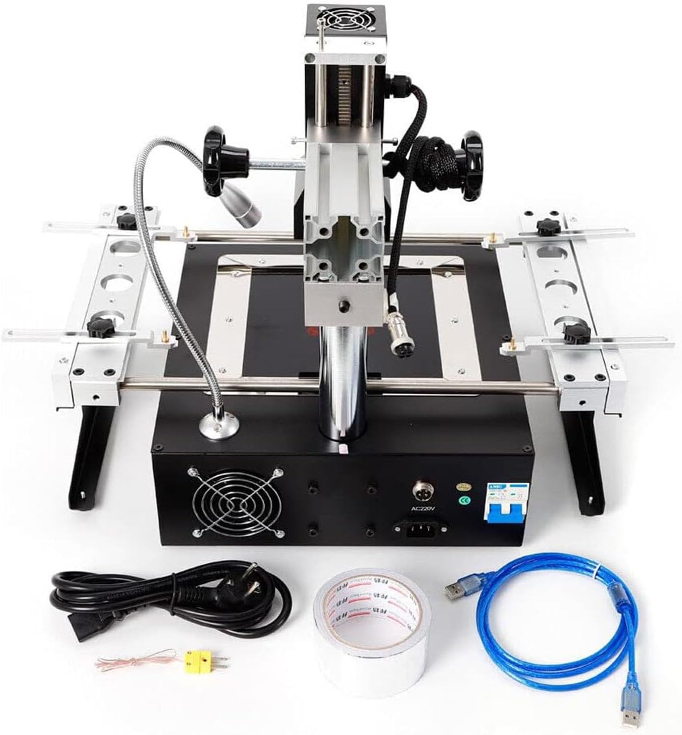
Immagine 4.4: Top-down view of the IR6500, illustrating the adjustable PCB mounting rails and the upper heating element assembly.
- Thermocouple Placement:
Connect the thermocouple to the designated input on the control panel. Position the thermocouple tip as close as possible to the component being reworked, ideally under the component or on an adjacent test point, to accurately monitor the temperature.
5. Istruzioni per l'uso
The IR6500 features a user-friendly control panel for precise temperature management.

Immagine 5.1: Close-up of the control panel, showing the "Lower TEMP Controller" and "Upside TEMP Controller" displays, along with various buttons for programming, manual control, and start/stop functions. Also visible are the Lighting Switch and Fan Switch.
- Accensione:
After completing the setup, switch the main circuit breaker (Image 4.3) to the ON position. The digital displays on the control panel will illuminate.
- Temperatura Profile Collocamento:
The rework station allows for setting 8 heating sections and 8 constant temperature sections. Use the "PROG" button and navigation keys on the "Upside TEMP Controller" to access and modify temperature profiles. You can save up to 10 distinct temperature curves for different applications.
- PV (valore di processo): Visualizza la temperatura attuale.
- SV (valore impostato): Visualizza la temperatura target.
- Refer to the detailed programming guide in the full manual for specific steps on creating and saving temperature profiles.
- Controllo manuale:
For quick adjustments or specific tasks, the "MAN" (Manual) mode can be engaged. This allows direct control over heater power output. Exercise caution when using manual mode to avoid overheating components.
- Starting the Rework Process:
Once the desired temperature profile is selected or manual settings are configured, press the Pulsante di avvio to initiate the heating cycle. Monitor the temperature displays and the component being reworked.
- Stopping the Rework Process:
To stop the heating cycle at any time, press the Pulsante di arresto. The heaters will turn off, and the cooling fan may activate to dissipate residual heat.
- Lighting and Fan Switches:
Utilizzare il Interruttore di illuminazione to turn on the integrated work light for better visibility. The Interruttore ventola controls the auxiliary cooling fan, which can be used to accelerate cooling after a rework cycle or for general ventilation.
6. Manutenzione
Regular maintenance ensures the longevity and optimal performance of your IR6500 BGA Infrared Rework Station.
- Pulizia:
After each use, allow the unit to cool completely. Use a soft, dry cloth to wipe down the exterior surfaces. For stubborn residues, a mild, non-abrasive cleaner can be used sparingly. Do not use solvents or harsh chemicals. Keep the heating elements and sensors free from dust and debris.
- Ventilatore e ventilazione:
Periodically inspect the cooling fan vents on the rear of the unit (Image 4.2) and clean any accumulated dust to ensure proper airflow.
- Magazzinaggio:
When not in use, store the rework station in a clean, dry environment, away from direct sunlight and extreme temperatures.
- Ispezione dei cavi:
Regularly check the power cable and other connections for any signs of wear, cuts, or damage. Replace damaged cables immediately.
7. Risoluzione Dei Problemi
This section addresses common issues you might encounter with your IR6500 BGA Infrared Rework Station.
| Problema | Possibile causa | Soluzione |
|---|---|---|
| L'unità non si accende. |
|
|
| Heaters not reaching set temperature. |
|
|
| PCB board is deforming. |
|
|
If you encounter issues not covered in this section, or if troubleshooting steps do not resolve the problem, please contact customer support.
8. Specifiche
| Parametro | Valore |
|---|---|
| Modello | IR6500 |
| Tipo di riscaldamento | Infrarossi (IR) |
| Dimensioni (L x P x A) | 475 x 480 x 420 mm (18.7 x 18.9 x 16.54 pollici) |
| Peso | 15 kg (41.8 libbre) |
| Alimentazione elettrica | 220V |
| Universal Power Consumption | 1250W |
| Potenza del riscaldatore superiore | 400W |
| Top Heater Dimensions | Dimensioni: 80 mm x 80 mm |
| Bottom Heater Power | 800W |
| Bottom Heater Dimensions | Dimensioni: 120 mm x 120 mm |
| Precisione del controllo della temperatura | ±0.5% |
| Applicable Chip Size | ≤70mm × 70mm |
| Applicable PCB Size | ≤400mm × 305mm |
| Tipo di visualizzazione | Display digitale a LED |
| Materiale | Metallo |
9. Garanzia e supporto
GBHJJ provides a standard manufacturer's warranty for this product. For specific warranty terms and conditions, please refer to the documentation included with your purchase or contact your retailer.
For technical support, troubleshooting assistance, or inquiries regarding parts and service, please contact GBHJJ customer service through your purchase platform or the official GBHJJ websito.