1. Introduzione
This manual provides detailed instructions for the installation, operation, and maintenance of your ZEBRONICS ROBUST Premium Gaming Chassis. Please read this manual thoroughly before beginning assembly to ensure proper setup and optimal performance. Keep this manual for future reference.

Immagine 1.1: anteriore view of the ZEBRONICS ROBUST Gaming Chassis, showcasing its tempered glass panels and illuminated interior fans.
2. Caratteristiche del prodotto
The ZEBRONICS ROBUST chassis is designed to provide a robust and aesthetically pleasing enclosure for your gaming PC components. Key features include:
- Glass-Finish Outlook: Front and side panels are constructed from tempered glass, offering a clear view of internal components and enhancing the chassis's visual appeal.
- Compatibilità della scheda madre: Supports mATX (Micro-ATX) and Mini ITX motherboard form factors.
- Ventilazione efficiente: Equipped with three pre-installed 120mm multicolor LED ring fans (two at the top, one at the rear) to ensure effective cooling and airflow.

Image 2.1: Illustration highlighting the three pre-installed 120mm multicolor LED ring fans for cooling.
- Multi-connettività: Front panel includes one USB 3.0 port, two USB 2.0 ports, and separate microphone and headphone jacks for convenient peripheral access.
- Slot di espansione: Features four expansion slots at the rear for installing add-on cards such as graphics cards or sound cards.
- Component Accommodation: Supports VGA cards up to 255mm in length and CPU coolers up to 165mm in height. The power supply unit (PSU) is designed for bottom installation.
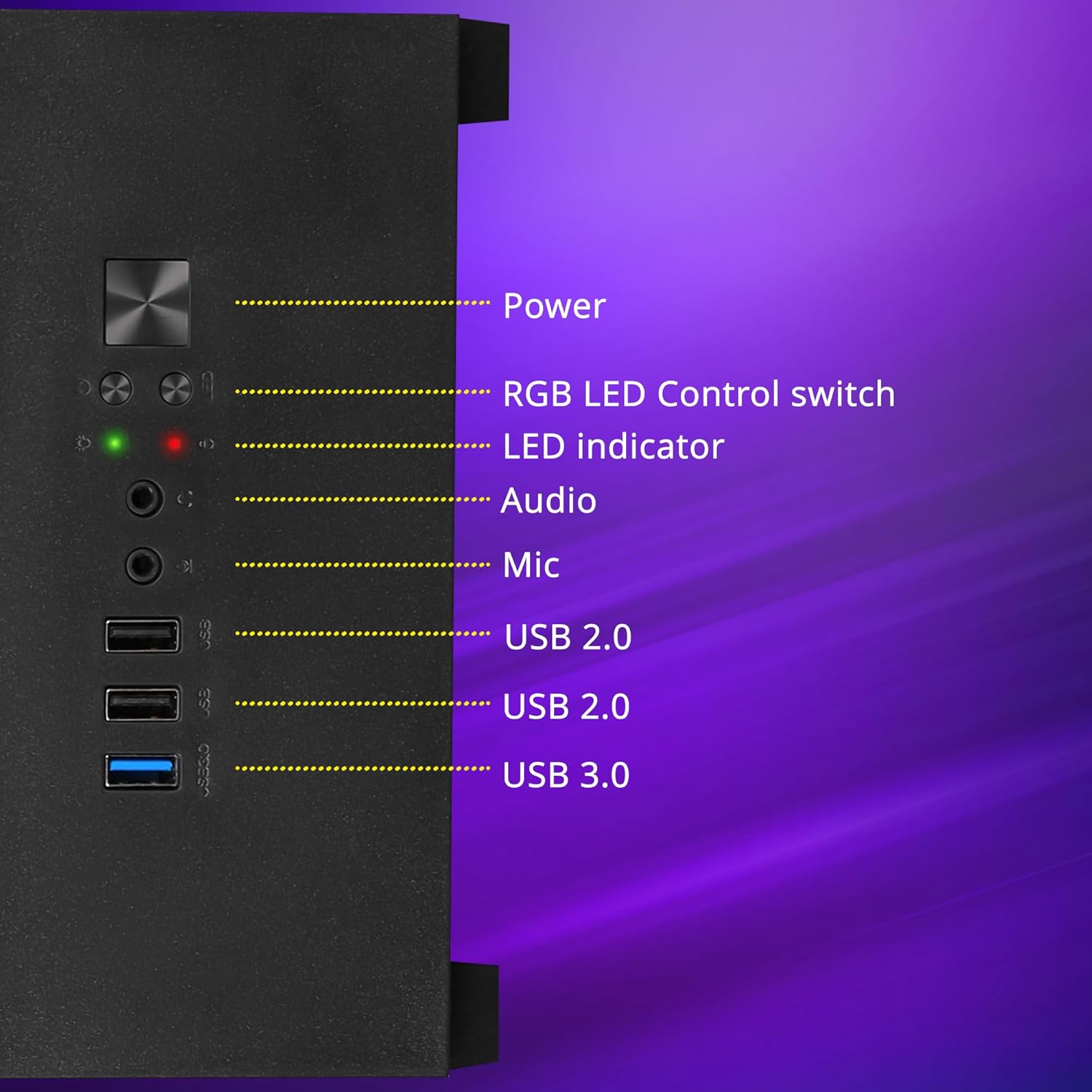
Immagine 2.2: Dettagliata view of the front panel I/O, showing the power button, RGB LED control switch, LED indicators, audio ports, and USB ports.

Image 2.3: Internal layout indicating the bottom-mounted power supply unit area and the four expansion slots for add-on cards.
- Optimized Cooling Design: Engineered for superior airflow to maintain optimal temperatures during extended use.

Image 2.4: Visual representation of the chassis's internal airflow path, designed for efficient heat dissipation.
- Filtrazione della polvere: Includes a magnetic dust filter at the top and a detachable dust filter at the bottom to prevent dust accumulation.
- Gestione dei cavi: Designed with features to facilitate effective cable organization, reducing clutter and improving airflow.

Image 2.5: Close-up of the top magnetic dust filter, demonstrating its easy removal for cleaning.
3. Specifiche
| Caratteristica | Dettaglio |
|---|---|
| Marca | ZEBRONICI |
| Modello | Zeb-Robust |
| Tipo di caso | Mid Tower |
| Compatibilità della scheda madre | mATX, Mini ITX |
| Ventole preinstallate | 3 x 120mm Multicolor LED Ring Fans (2 Top, 1 Rear) |
| Porte I / O anteriori | 1 x USB 3.0, 2 x USB 2.0, 1 x Mic, 1 x Headphone, Power, RGB LED Control Switch |
| Slot di espansione | 4 |
| Lunghezza massima della scheda VGA | 255mm |
| Altezza massima del dissipatore della CPU | 165mm |
| Montaggio dell'alimentatore | Metter il fondo a |
| Filtri antipolvere | Top Magnetic, Bottom Detachable |
4. Guida all'installazione
Follow these steps to assemble your computer components within the ZEBRONICS ROBUST chassis.
4.1. Unpacking and Panel Removal
- Estrarre con cautela il telaio dall'imballaggio.
- Posizionare il telaio su una superficie stabile e piana.
- Locate the thumbscrews on the rear of the chassis securing the tempered glass side panel. Unscrew them and carefully remove the side panel. Set it aside in a safe place to prevent damage.
- Repeat for the other side panel if necessary for easier access.
4.2. Installazione della scheda madre

Image 4.1: Chassis interior indicating support for mATX and Mini ITX motherboard sizes.
- Install the I/O shield that came with your motherboard into the corresponding opening at the rear of the chassis.
- Align your mATX or Mini ITX motherboard with the pre-installed standoffs inside the chassis.
- Secure the motherboard using the appropriate screws. Do not overtighten.
4.3. Installazione dell'unità di alimentazione (PSU)
- Position your PSU in the designated bottom compartment of the chassis.
- Ensure the PSU fan is facing downwards (if the chassis has a bottom vent) or upwards, depending on your cooling preference and chassis design.
- Secure the PSU to the chassis using the screws provided with your PSU.
4.4. Installazione dell'unità di archiviazione
The chassis typically includes bays for 2.5-inch SSDs and 3.5-inch HDDs. Refer to your chassis's internal layout for specific mounting points.
- Locate the drive bays or mounting brackets.
- Install your SSDs or HDDs into the appropriate bays/brackets and secure them with screws.
4.5. Graphics Card (VGA) and Expansion Card Installation
- Rimuovere le coperture degli slot di espansione necessari dalla parte posteriore dello chassis.
- Insert your graphics card or other expansion cards into the corresponding PCIe slots on your motherboard.
- Secure the cards with screws to the chassis.
4.6. Collegamento dei cavi del pannello frontale
Connect the front panel cables (USB, audio, power switch, reset switch, LED indicators) from the chassis to the corresponding headers on your motherboard. Refer to your motherboard manual for exact header locations.
4.7. Gestione dei cavi
Utilizzate i fori per il passaggio dei cavi e i punti di fissaggio dietro il vassoio della scheda madre per organizzare e fissare i cavi. Questo migliora il flusso d'aria e l'estetica.
4.8. Reattaching Panels
Once all components are installed and cables are managed, carefully reattach the side panels and secure them with the thumbscrews.
5. Istruzioni per l'uso
5.1. Accensione/Spegnimento
- Assicurarsi che tutte le periferiche esterne (monitor, tastiera, mouse) siano collegate.
- Collegare il cavo di alimentazione all'alimentatore e a una presa a muro.
- Press the power button on the front panel of the chassis to turn on your computer.
- To turn off, use the operating system's shutdown function or press and hold the power button for several seconds.
5.2. LED Fan Control
The chassis features an RGB LED Control switch on the front panel. Press this button to cycle through various lighting modes and colors for the pre-installed LED fans.
6. Manutenzione
Regular maintenance helps ensure the longevity and optimal performance of your chassis and its components.
6.1. Pulizia dei filtri antipolvere
- Periodically remove the top magnetic dust filter and the bottom detachable dust filter.
- Clean the filters using compressed air, a soft brush, or by rinsing with water (ensure they are completely dry before reinstallation).
- Reattach the dust filters.
6.2. Pulizia generale
- Use a soft, dry cloth to wipe down the exterior surfaces of the chassis, including the tempered glass panels.
- For stubborn smudges on glass, a mild glass cleaner applied to a cloth (not directly to the glass) can be used.
- Evitare l'uso di detergenti abrasivi o solventi, poiché potrebbero danneggiare la finitura.
7. Risoluzione Dei Problemi
Questa sezione affronta i problemi più comuni che potresti incontrare.
7.1. Nessun potere
- Assicurarsi che il cavo di alimentazione sia collegato saldamente sia all'alimentatore che alla presa a muro.
- Check that the power switch on the PSU itself is in the 'ON' position.
- Verificare che il cavo dell'interruttore di alimentazione del pannello frontale sia collegato correttamente al connettore della scheda madre.
7.2. Fans Not Spinning / LEDs Not Working
- Check that the fan power cables are securely connected to the motherboard or a fan controller.
- Ensure the RGB LED control cable (if separate from fan power) is properly connected.
- Press the RGB LED Control switch on the front panel to cycle through modes or turn on the LEDs.
7.3. Front Panel USB/Audio Ports Not Functioning
- Verificare che i cavi USB e audio del pannello frontale siano collegati correttamente ai rispettivi connettori sulla scheda madre.
- Check your operating system's device manager and audio settings to ensure drivers are installed and devices are enabled.
8. Garanzia e supporto
For warranty information and technical support, please refer to the documentation provided with your purchase or visit the official ZEBRONICS websito. Conservare la prova d'acquisto per eventuali reclami in garanzia.
For further assistance, you may contact ZEBRONICS customer support through their official channels.