Mastech MS2101
Mastech MS2101 AC/DC Digital Clamp Manuale utente del misuratore
Modello: MS2101 | Marca: Mastech
1. Informazioni importanti sulla sicurezza
Please read and understand all safety information and operating instructions before using this instrument. Improper use may result in electric shock or damage to the meter. Always adhere to local and national safety codes.
- Non superare i valori massimi di input specificati per ciascuna funzione.
- Ensure the test leads are properly connected and in good condition before making any measurements.
- Non utilizzare il misuratore se appare danneggiato o se l'isolamento dei puntali di prova è compromesso.
- Prestare estrema attenzione quando si lavora con il voltagsuperiori a 30 V CA RMS, 42 V di picco o 60 V CC. Questi voltagrappresentano un rischio di scossa elettrica.
- Scollegare sempre l'alimentazione del circuito e scaricare tutti i componenti ad alto volumetagcondensatori prima di misurare la resistenza, la continuità, i diodi o la capacità.
- Per garantire letture accurate, sostituire immediatamente le batterie quando compare l'indicatore di batteria scarica.
- This device is rated for CAT III 600V and CAT II 1000V. Adhere to these safety categories.
2. Prodotto finitoview
The Mastech MS2101 is a versatile AC/DC digital clamp meter designed for accurate measurement of current, voltage, resistance, capacitance, frequency, and temperature. It features auto-ranging capabilities and a clear digital display, making it suitable for both domestic and industrial electrical testing.
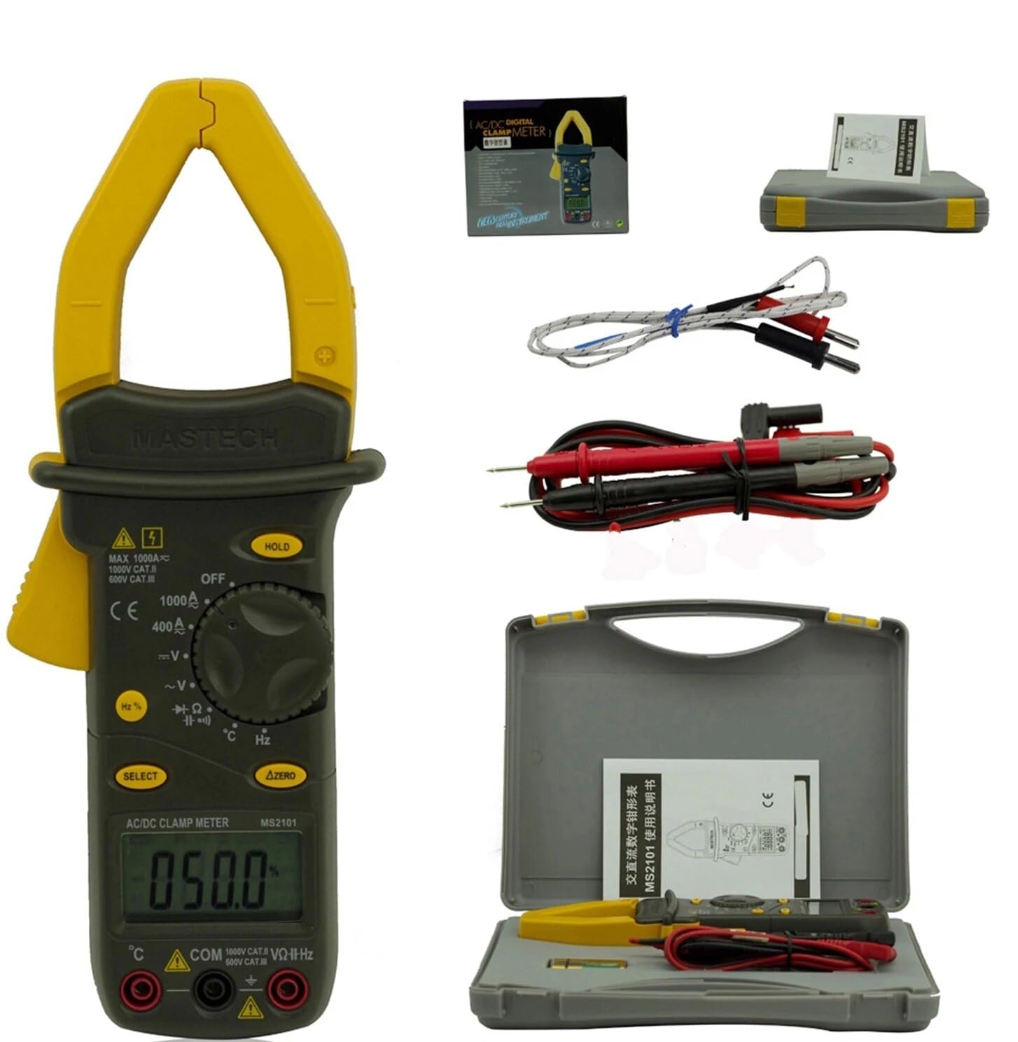
Image: Mastech MS2101 clamp meter with included test leads, temperature probe, and carrying case.
2.1 Caratteristiche principali
- Display: 4000 conta
- Jaw Opening: Φ42mm / 1.7 inches
- Gamma automatica e manuale
- Funzione di spegnimento automatico
- Diodo aperto Voltage: 2.2 V
- Continuity Buzzer: Activates at <50±20Ω
- Funzione Hold Data
- Indicatore di batteria scarica
3. Contenuto della confezione
Dopo aver aperto la confezione, verificare che tutti gli articoli elencati di seguito siano presenti e in buone condizioni.

Image: Contents of the Mastech MS2101 package, including the meter, test leads, and documentation.
- Mastech MS2101 AC/DC Digital Clamp metro
- Cavi di prova (una coppia)
- K-Type Thermocouple (for temperature measurement)
- Borsa per il trasporto
- Certificato di calibrazione
- Guida rapida
- Batterie (2 x LR44, incluse)
4. Layout e controlli del dispositivo
Familiarize yourself with the various parts and controls of your MS2101 clamp metro.

Immagine: Frontale view of the Mastech MS2101, highlighting the display, rotary switch, and function buttons.
- Cl Current attualeamp Mascella: Utilizzato per la misurazione della corrente CA/CC senza contatto.
- Grilletto a mascella: Squeeze to open the current clamp mascella.
- Interruttore rotante: Selects the desired measurement function (OFF, V, A, Ω, Capacitance, Hz, Diode, Continuity, Temperature).
- Schermo LCD: Mostra le letture delle misurazioni, le unità e gli indicatori di funzione.
- Pulsante ATTESA: Blocca la lettura corrente sul display.
- Pulsante SELEZIONA: Toggles between AC/DC modes or different functions within a rotary switch position (e.g., Diode/Continuity, AC/DC VoltagE).
- ΔZERO Button: Used to zero out DC current readings or relative measurements.
- Jack di ingresso COM: Ingresso comune (negativo) per i puntali di prova.
- Jack di ingresso VΩHz: Input positivo per voltage misure di resistenza, frequenza, capacità, diodi e continuità.
- Temperature Input Jack: Specific input for the K-type thermocouple.
5. Configurazione iniziale
5.1 Installazione della batteria
The Mastech MS2101 requires two LR44 batteries for operation. These are typically included in the package.

Immagine: Indietro view of the Mastech MS2101, indicating the location of the battery compartment screws.
- Assicurarsi che il misuratore sia spento.
- Individuare il vano batterie sul retro del misuratore.
- Use a screwdriver to remove the screws securing the battery cover.
- Rimuovere con cautela il coperchio della batteria.
- Insert two LR44 batteries, observing the correct polarity (+ and -) as indicated inside the compartment.
- Riposizionare il coperchio della batteria e fissarlo con le viti.
6. Istruzioni per l'uso
6.1 Accensione/spegnimento
To power on the meter, rotate the rotary switch from the 'OFF' position to any desired measurement function. To power off, rotate the switch back to 'OFF'.
6.2 Selezione della funzione
Turn the rotary switch to the desired measurement function. For functions with multiple modes (e.g., AC/DC Voltage, Diode/Continuity), press the 'SELECT' button to toggle between them.
6.3 Misurazione della corrente CA/CC
- Rotate the switch to the 'A' (Current) position.
- Press 'SELECT' to choose between AC or DC current measurement.
- Premere il grilletto della mascella per aprire il clamp mascella.
- Racchiudere solo un conduttore del circuito all'interno del clamp mascella. Assicurarsi che la mascella sia completamente chiusa.
- Leggere il valore corrente sul display LCD.
- For DC current, use the 'ΔZERO' button to zero the display before measurement if necessary.
6.4 Misurazione del volume AC/DCtage
- Rotate the switch to the 'V' (Voltage) posizione.
- Press 'SELECT' to choose between AC or DC voltage misurazione.
- Inserire il puntale di prova rosso nel jack 'VΩHz' e il puntale di prova nero nel jack 'COM'.
- Collegare le sonde di prova in parallelo al circuito o al componente che si desidera misurare.
- Leggi il vol.tage valore sul display LCD.
6.5 Misurazione della resistenza
- Ruotare l'interruttore in posizione 'Ω' (Resistenza).
- Inserire il puntale di prova rosso nel jack 'VΩHz' e il puntale di prova nero nel jack 'COM'.
- Ensure the circuit or component is de-energized before connecting the test probes across it.
- Leggere il valore della resistenza sul display LCD.
6.6 Misurare la capacità
- Rotate the switch to the 'Capacitance' position.
- Inserire il puntale di prova rosso nel jack 'VΩHz' e il puntale di prova nero nel jack 'COM'.
- Ensure the capacitor is fully discharged before connecting the test probes across it.
- Leggere il valore della capacità sul display LCD.
6.7 Measuring Frequency/Duty Cycle
- Rotate the switch to the 'Hz' (Frequency) position.
- Inserire il puntale di prova rosso nel jack 'VΩHz' e il puntale di prova nero nel jack 'COM'.
- Collegare le sonde di prova alla sorgente del segnale.
- Read the frequency or duty cycle value on the LCD display. Press 'SELECT' to toggle between frequency and duty cycle.
6.8 Test diodi
- Rotate the switch to the Diode/Continuity position. Press 'SELECT' until the diode symbol appears.
- Inserire il puntale di prova rosso nel jack 'VΩHz' e il puntale di prova nero nel jack 'COM'.
- Collegare la sonda rossa all'anodo e la sonda nera al catodo del diodo.
- Leggi il vol avantitage drop on the display. Reverse the probes to check for open circuit (OL) in reverse bias.
6.9 Prova di continuità
- Rotate the switch to the Diode/Continuity position. Press 'SELECT' until the continuity buzzer symbol appears.
- Inserire il puntale di prova rosso nel jack 'VΩHz' e il puntale di prova nero nel jack 'COM'.
- Collegare le sonde di prova al circuito o al componente.
- Se la resistenza è inferiore a circa 50Ω, il cicalino suonerà, indicando la continuità.
6.10 Misurazione della temperatura
- Rotate the switch to the '°C/°F' (Temperature) position.
- Insert the K-type thermocouple into the dedicated temperature input jacks, observing polarity.
- Posizionare la punta della termocoppia sopra o vicino all'oggetto di cui si desidera misurare la temperatura.
- Read the temperature on the LCD display. Press 'SELECT' to toggle between Celsius and Fahrenheit.
6.11 Funzione di conservazione dei dati
Premere il pulsante 'HOLD' per bloccare la lettura corrente sul display. Premerlo nuovamente per disattivare il blocco e riprendere le misurazioni in tempo reale.
6.12 Zeroing (ΔZERO) Function
In DC current mode, press the 'ΔZERO' button to zero the display before making a measurement. This compensates for any residual magnetic fields or offsets, ensuring more accurate DC current readings.
6.13 Spegnimento automatico
The meter will automatically power off after approximately 15 minutes of inactivity to conserve battery life. To reactivate, turn the rotary switch to 'OFF' and then back to the desired function.
7. Manutenzione
7.1 Pulizia
Pulisci il contatore casing con annuncioamp panno e un detergente delicato. Non utilizzare abrasivi o solventi. Assicurarsi che il misuratore sia completamente asciutto prima dell'uso.
7.2 Sostituzione della batteria
When the low battery indicator appears on the display, replace the batteries as described in Section 5.1. Always use two new LR44 batteries.
7.3 Conservazione
Se il misuratore non viene utilizzato per un periodo prolungato, rimuovere le batterie per evitare perdite e danni. Conservare il misuratore in un luogo fresco e asciutto, lontano dalla luce solare diretta e da temperature estreme.
8. Risoluzione Dei Problemi
- Il misuratore non si accende: Controllare l'installazione delle batterie e assicurarsi che non siano scariche.
- Nessuna lettura o 'OL' visualizzato: Assicurarsi che i puntali di prova siano collegati correttamente e che facciano un buon contatto. Per le misurazioni di corrente, assicurarsi che solo un conduttore sia all'interno del circuito.amp jaw. For resistance/continuity, ensure the circuit is de-energized. 'OL' (Overload) indicates the measured value is beyond the meter's range.
- Letture imprecise: Check battery level. Ensure the correct function is selected. For DC current, use the 'ΔZERO' function.
- Buzzer not sounding in continuity mode: The resistance may be too high (above 50Ω), or the circuit is open.
9. Specifiche tecniche
Detailed specifications for the Mastech MS2101 clamp meter are provided below.

Image: Table detailing the measurement ranges, resolutions, and accuracies of the Mastech MS2101.
| Misurazione | Allineare | Risoluzione | Precisione |
|---|---|---|---|
| Volume DCtage | 400mV/4V/40V/400V 1000V | 0.1 mV/1 mV/10 mV/0.1 V 1V | ±(0.7%+1) ±(0.8%+3) |
| Volume ACtage | 4V/40V/400V 750V | 1 mV/10 mV/0.1 V 1V | ±(0.8%+5) ±(1.0%+10) |
| Corrente continua | 400A/1000A | 0.1A/1A | ±(3.0%+3) |
| Corrente alternata | 400A/1000A | 0.1A/1A | ±(3.0%+3) |
| Resistenza | 400Ω/4kΩ/40kΩ/400kΩ/4MΩ 40 MΩ | 0.1Ω/1Ω/10Ω/100Ω/1kΩ 10kΩ | ±(1.2%+1) ±(2.0%+3) |
| Capacità | 4 nF/40 nF/400 nF 4 µF/40 µF/100 µF | 1 pF/10 pF/0.1 nF 1 nF/10 nF/100 nF | ±(4.0%+10) ±(4.0%+10) |
| Frequenza | 40Hz/400Hz/4kHz/40kHz/100kHz | 0.01Hz/0.1Hz/1Hz/10Hz/0.1kHz | ±(2.0%+1) |
| Ciclo di lavoro | 0.1% ~ 99.9% | 0.10% | ±(2.0%+2) |
| Temperatura | Temperatura ambiente -40°C ~ 0°C Temperatura ambiente: da 1°C a 400°C Temperatura ambiente: da 401°C a 750°C | 1°C 1°C 1°C | ±(1.0%+6) ±(1.0%+3) ±(1.0%+5) |
| Display | 4000 conteggi | ||
| Apertura della mascella | 42 mm / 1.7 pollici | ||
| Buzzer di continuità | <50±20Ω | ||
| Diodo aperto Voltage | 2.2V | ||
| Fonte di alimentazione | 2 batterie LR44 | ||
| Dimensioni (L x P x A) | 7.87 x 5.91 x 9.84 pollici | ||
| Peso | 1 chilogrammo (2.2 libbre) | ||
10. Garanzia e supporto
The Mastech MS2101 Digital Clamp Meter comes with a 1-year warranty from the date of purchase, covering manufacturing defects. Please retain your proof of purchase for warranty claims.
For technical support, product information, or warranty inquiries, please visit the official Mastech websito o contattare il loro servizio clienti:
- Official Mastech Websito: www.mastech-group.com
- Pagina di supporto: http://www.mastech-group.com/support.php?n=0
Ask a question about this manual
Ask about setup, troubleshooting, compatibility, parts, safety, or missing instructions. Manuals+ will review the question and use this page’s manual context to help answer it.