
YELUFT BLDC
YELUFT DC 6-60V 400W BLDC Three-Phase Brushless Motor Controller Instruction Manual
Model: BLDC
1. Introduzione
This manual provides detailed instructions for the installation, operation, and maintenance of the YELUFT DC 6-60V 400W BLDC Three-Phase Brushless Motor Controller. This controller is designed for use with DC brushless Hall motors with an electric angle of 120 degrees, offering wide voltage compatibility (6-60V) and high power output up to 400W. It supports various control methods including PLC 0-5V analog signal and PWM control, and features forward, reverse, stop, and brake functions.

Image 1.1: The YELUFT DC 6-60V 400W BLDC Three-Phase Brushless Motor Controller board with included wires.
2. Informazioni sulla sicurezza
- Always disconnect power before making any connections or disconnections to prevent electric shock or damage to the device.
- Ensure proper ventilation to prevent overheating, especially during high-power operation.
- Verify all wiring connections are correct and secure before applying power. Incorrect wiring can cause damage to the controller, motor, or power supply.
- This controller is designed for 120-degree electric angle DC brushless Hall motors only. Using it with other motor types may result in malfunction or damage.
- Keep the device away from moisture, dust, and corrosive environments.
- Non superare il volume massimotage (60V) or power (400W) ratings.
3. Prodotto finitoview
The YELUFT BLDC motor controller features a compact design with clearly labeled terminals for easy integration. It includes a heatsink for thermal management and a wiring harness for Hall sensor connections.

Immagine 3.1: anteriore view of the controller showing terminals and components, and the back view showing the heatsink.
Contenuto della confezione:
- 1 x YELUFT DC 6-60V 400W BLDC Three-Phase Brushless Motor Controller (Dimensions: 2.48" x 1.77" x 1.22")
- 1 x Hall Sensor Wiring Harness (Length: 4.1")
4. Specifiche
| Parametro | Valore |
|---|---|
| Volume di eserciziotage | CC 6V - 60V |
| Corrente massima | Rated 16A, Peak 20A |
| Potenza massima | 400W |
| Tipo di controllo | DC Three-Phase Brushless Hall Motor Controller |
| Motor Electric Angle | 120 degrees (Hall motor required) |
| Speed Control Input | PLC 0-5V analog signal, PWM control (amplitude 2.5-5V, frequency 1K-20KHz) |
| Funzioni | Forward, Reverse, Stop, Brake |
| Dimensioni | 63mm x 45mm x 31mm (2.48 "x 1.77" x 1.22 ") |
| Peso | Circa 3.2 once (90 g) |

Image 4.1: Visual representation of key product parameters and the essential note regarding Hall sensor requirement.
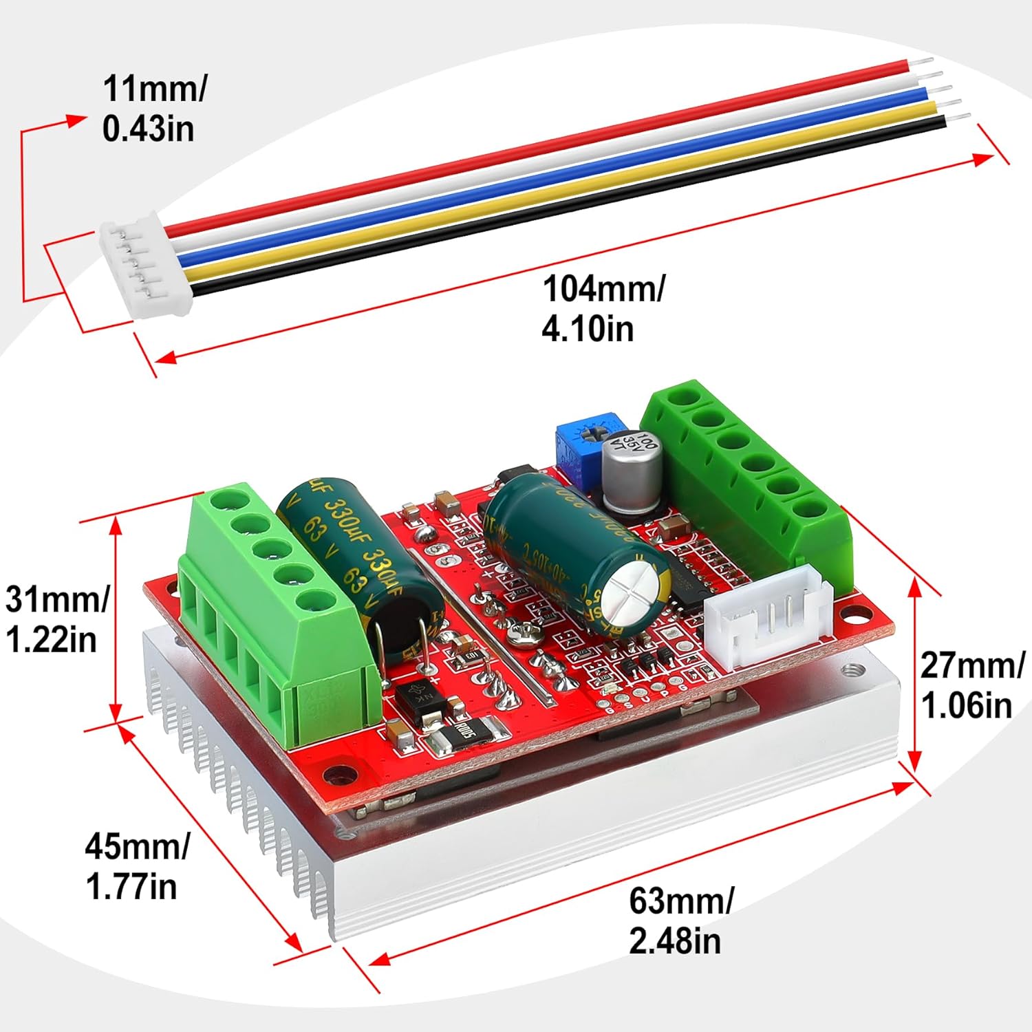
Image 4.2: Detailed dimensions of the controller board and the included Hall sensor wiring harness.
5. Configurazione e cablaggio
Carefully follow the wiring diagram to ensure correct connections. Incorrect wiring can damage the controller or motor.
Schema elettrico finitoview:
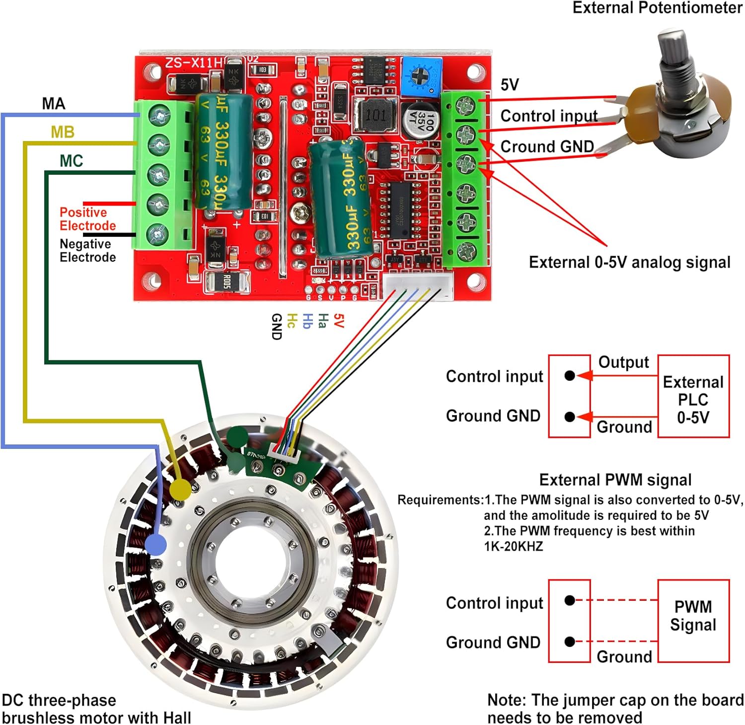
Image 5.1: Comprehensive wiring diagram illustrating connections for power, motor phases, Hall sensors, and control inputs (potentiometer, PLC, PWM).
Passaggi di connessione:
- Alimentazione (VCC, GND): Connect your DC power supply (6-60V) to the VCC (positive) and GND (negative) terminals on the controller. Ensure the polarity is correct.
- Motor Phase Lines (MA, MB, MC): Connect the three phase wires from your brushless motor to the MA, MB, and MC terminals on the controller. The order of these connections may affect motor rotation direction.
- Hall Sensor Connections (Ha, Hb, Hc, +5V, GND):
- Connect the +5V and GND wires from the Hall sensor harness to the corresponding +5V and GND pins on the controller's Hall sensor interface.
- Connect the Ha, Hb, Hc signal wires from the Hall sensor harness to the Ha, Hb, Hc pins on the controller. Ensure these correspond correctly to the motor's Hall sensor outputs.
- Nota: This controller requires a Hall sensor motor to function. If your motor does not have Hall sensors, this controller will not operate.
- Speed Control Input:
- External Potentiometer (0-5V Analog): Connect the potentiometer's output to the 'Control input' terminal and its ground to the 'Ground GND' terminal. The controller provides a 5V supply for the potentiometer.
- External PLC 0-5V Analog Signal: Connect the PLC output to the 'Control input' terminal and its ground to the 'Ground GND' terminal.
- Segnale PWM esterno: Connect the PWM signal to the 'Control input' terminal and its ground to the 'Ground GND' terminal. The PWM signal should have an amplitude of 2.5-5V and a frequency between 1K-20KHz.
- Nota: If using an external speed control signal, the jumper cap on the board for the on-board potentiometer must be removed.
- Direction Control (DIR): Connect a switch or control signal to the 'DIR' terminal. Shorting 'DIR' to ground will typically reverse the motor direction.
- Stop Control (STOP): Connect a switch or control signal to the 'STOP' terminal. Shorting 'STOP' to ground will stop the motor.
- Brake Control (BRAKE): Connect a switch or control signal to the 'BRAKE' terminal. Shorting 'BRAKE' to ground will activate the motor brake function.
- SC Speed Pulse Signal Output: This terminal provides a speed pulse signal output, which can be used for external speed monitoring.
6. Istruzioni per l'uso
Once all connections are securely made and verified, power on the controller. The motor should be ready for operation based on your control inputs.
Funzioni:
- Controllo della velocità: Adjust the connected potentiometer or provide the appropriate 0-5V analog/PWM signal to the 'Control input' to vary the motor speed.
- Direction Control (DIR): Toggle the 'DIR' input (e.g., connect to ground) to switch between forward and reverse rotation.
- Stop Function (STOP): Activate the 'STOP' input (e.g., connect to ground) to bring the motor to a halt.
- Brake Function (BRAKE): Activate the 'BRAKE' input (e.g., connect to ground) to engage the motor's braking mechanism.
- Protezione da sovracorrente: The controller is equipped with overcurrent protection to safeguard against excessive current draw.
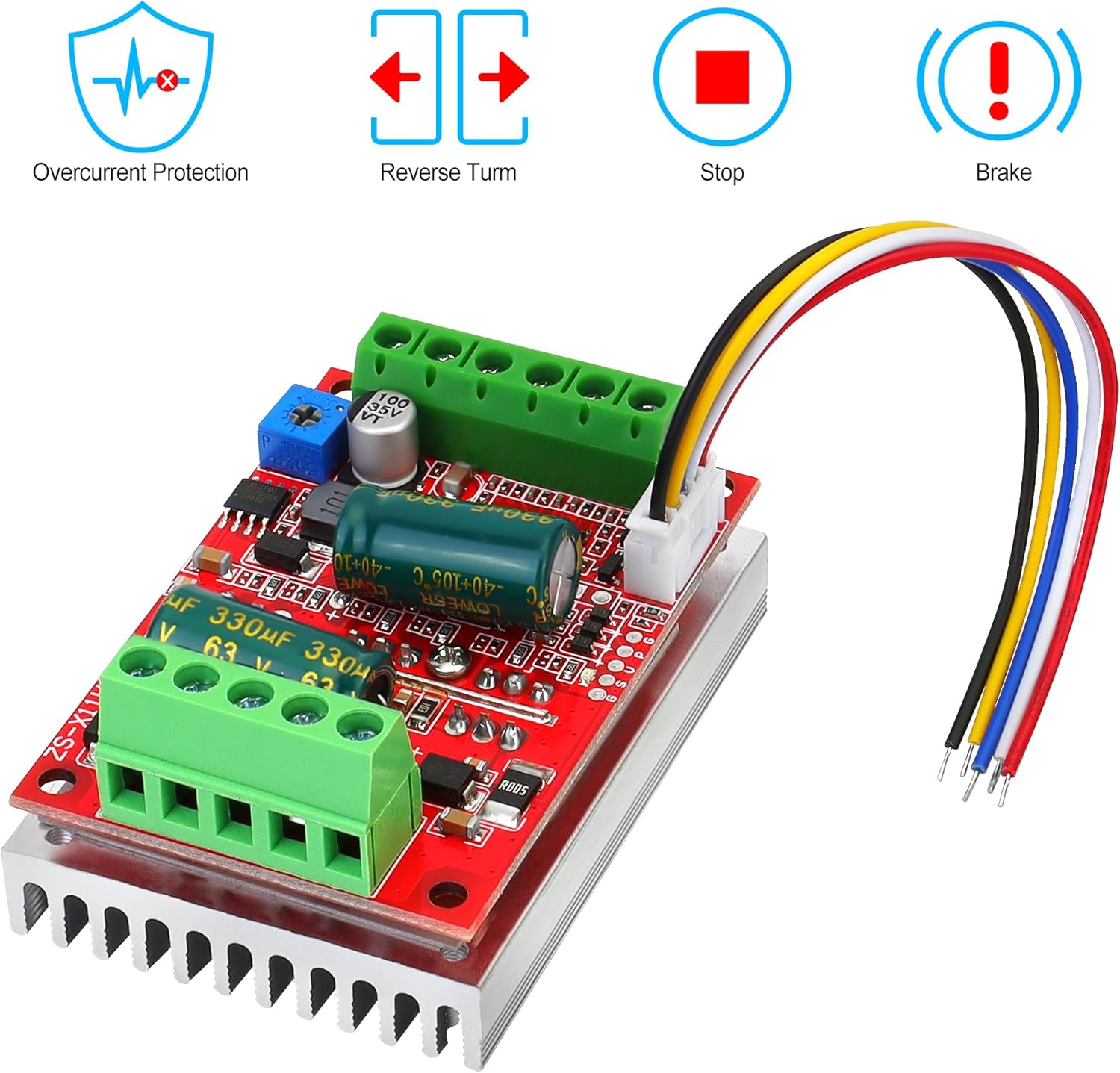
Image 6.1: Visual indicators for key operational features: Overcurrent Protection, Reverse Turn, Stop, and Brake.
7. Manutenzione
- Mantenere il controller pulito e privo di polvere e detriti. Utilizzare un panno morbido e asciutto per la pulizia.
- Regularly inspect all wiring connections for looseness or damage. Tighten any loose connections.
- Ensure adequate airflow around the heatsink to maintain optimal operating temperature.
- Avoid exposing the controller to extreme temperatures or humidity.
8. Risoluzione Dei Problemi
- Il motore non gira:
- Controllare i collegamenti dell'alimentazione e il volumetage.
- Verify all motor phase (MA, MB, MC) and Hall sensor (Ha, Hb, Hc, +5V, GND) connections are correct and secure.
- Ensure the motor is a 120-degree electric angle DC brushless Hall motor.
- Confirm the speed control input is active and providing a valid signal (0-5V or PWM).
- Motor spins slowly or inconsistently:
- Check the quality and stability of the speed control input signal.
- Inspect Hall sensor connections for intermittent contact.
- Assicurarsi che il motore non sia sovraccarico.
- Motor does not stop or brake properly:
- Verify the 'STOP' or 'BRAKE' control input connections are functioning correctly (e.g., shorting to ground).
- If using a Hall throttle, ensure its minimum output voltage allows the motor to fully stop. Some Hall throttles may require external modification (e.g., adding diodes) to achieve a true 0V equivalent at idle.
- Surriscaldamento del controller:
- Ensure adequate ventilation around the heatsink.
- Check if the motor is drawing excessive current, potentially indicating an overload or fault.
9. Garanzia e supporto
YELUFT products are designed for reliability and performance. For technical support, warranty claims, or further assistance, please contact your retailer or the manufacturer directly through the contact information provided at the point of purchase. Please have your product model number and purchase details ready when contacting support.
Ask a question about this manual
Ask about setup, troubleshooting, compatibility, parts, safety, or missing instructions. Manuals+ will review the question and use this page’s manual context to help answer it.