1. Introduzione
This user manual provides comprehensive instructions for the AITRIP ESP32-2432S024 2.4-inch TFT LCD Display Module. This module integrates an ESP-WROOM-32 development board with a 2.4-inch IPS resistive touch screen, designed for various embedded applications, including IoT devices, smart home automation, and robotics. Please read this manual thoroughly before operating the device.
2. Prodotto finitoview
2.1 Caratteristiche principali
- Low-power dual-core 32-bit CPU, operating up to 240MHz.
- Integrated 2.4-inch IPS Resistive Touch Screen with 240x320 resolution.
- Built-in 520 KB SRAM and 448KB ROM.
- Supports UART, SPI, I2C, PWM, ADC, and DAC interfaces.
- Compatibility with OV2640 and OV7670 cameras (requires FPC connector).
- Wi-Fi upload capability and support for TF cards (up to 32GB).
- Multiple sleep modes for power efficiency.
- STA/AP/STA+AP working modes.
- Onboard PCB antenna with 2dBi gain.
- Image output formats: JPEG (OV2640 only), BMP, GRAYSCALE.
2.2 Specifiche
| Specificazione | Valore |
|---|---|
| Processore | Dual-core 32-bit CPU, 240 MHz |
| Memoria RAM | 520 KB di SRAM |
| ROM | 448 KB di ROM |
| Dimensioni dello schermo | 2.4 pollici |
| Risoluzione | 240x320 pixel |
| Tipo di visualizzazione | IPS Resistive Touch TFT LCD |
| Connettività wireless | Wi-Fi (802.11n), Bluetooth |
| Sistema operativo | RTOS gratuito |
| Volume di lavorotage | 4.75-5.25 V |
| Temperatura di esercizio | -20 ℃ a 70 ℃ |
| Spia flash | 32Mbit (default) |
| Porte IO | 9 |
| Velocità della porta seriale | 115200 bps (predefinito) |
| Antenna | Onboard PCB antenna, 2dBi gain |
| Consumo energetico (flash spento) | 180mA @ 5V |
| Consumo energetico (luminosità massima del flash) | 310mA @ 5V |
| Deep-sleep Power Consumption | 6mA@5V (Min) |
2.3 Contenuto della confezione
- AITRIP ESP32-2432S024 2.4-inch TFT LCD Display Module with Touch (Quantity as per purchase, e.g., 2 modules for a 2-pack)
- USB-A to USB-C Cable (Quantity as per purchase)
- 2-pin JST connector cable (Quantity as per purchase)
- Stylus (Quantity as per purchase)

Image 1: Contents of the AITRIP ESP32-2432S024 2-pack, showing two display modules, two USB-C cables, two 2-pin JST cables, and two white styluses.
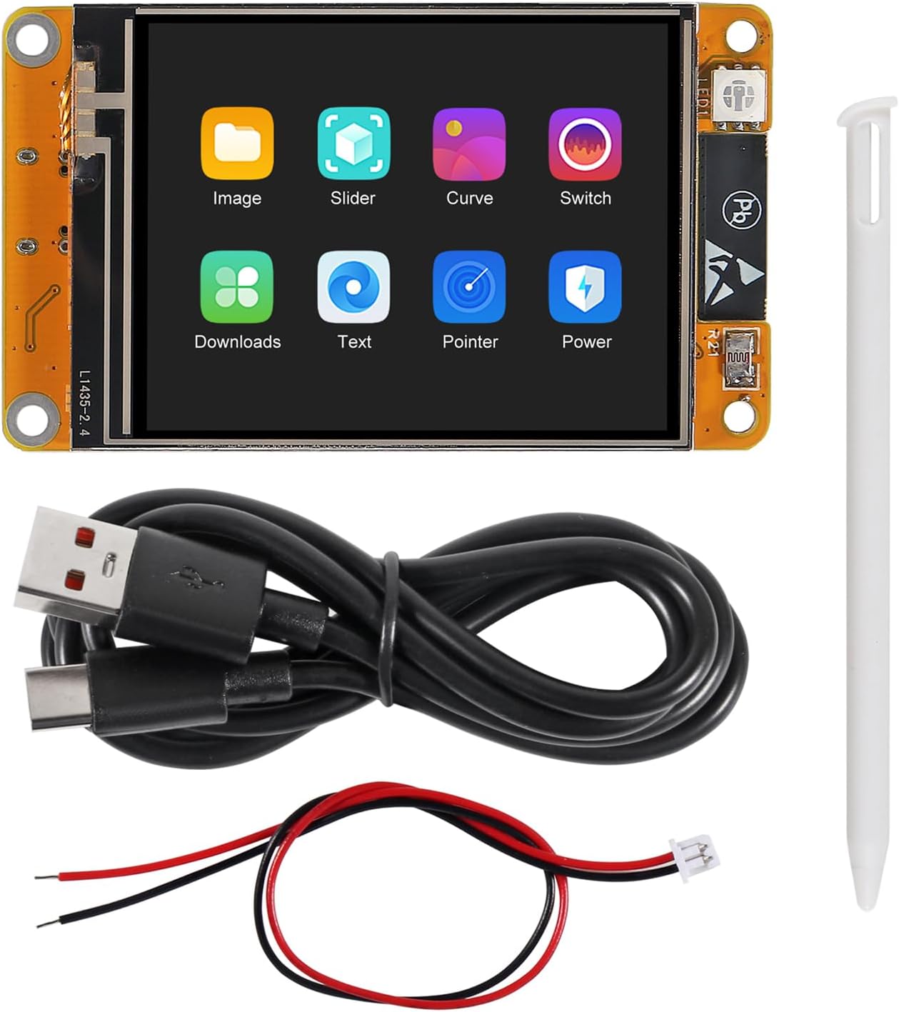
Image 2: A single AITRIP ESP32-2432S024 module and its accessories, including a USB-C cable, a 2-pin JST cable, and a white stylus.
3. Istruzioni per l'installazione
Setting up the AITRIP ESP32-2432S024 module involves connecting it to a computer, installing necessary drivers and development environments, and uploading firmware. Due to the open-source nature of ESP32 development, specific steps may vary based on your chosen development environment (e.g., Arduino IDE, ESP-IDF, ESPHome).
3.1 Connessione iniziale
- Connect the module to your computer using the provided USB-C cable. Ensure the cable is securely connected to both the module's USB-C port and your computer's USB port.
- For initial power-up or programming, some users have reported issues with direct USB-C power. Alternative power methods include:
- Powering via the 5V pin on the P1 connector (next to the USB-C port) using an external 5V power supply.
- Using a charged LiPo battery connected to the 1.25mm 2-pin JST connector.
- Creating a custom cable to connect BAT+ to the V+ of P1 for stable power during USB connection.

Image 3: The ESP32-2432S024 module connected to a laptop, demonstrating a typical development setup.
3.2 Software Environment Setup (Arduino IDE Example)
- Install the Arduino IDE from the official Arduino websito.
- Add ESP32 board support to the Arduino IDE:
- Vai a File > Preferenze.
- In "Additional Board Manager URLs", add:
https://raw.githubusercontent.com/espressif/arduino-esp32/gh-pages/package_esp32_index.json - Vai a Strumenti > Bacheca > Gestore bacheca. Cercare "ESP32" e installare il pacchetto "esp32 by Espressif Systems".
- Install necessary libraries for the display and touch functionality. Common libraries include:
- TFT_eSPI Library: This library is highly recommended for TFT displays. Install it via Sketch > Include Library > Manage Libraries.
- Touch Screen Library: For the resistive touch screen, libraries like XPT2046_Touchscreen potrebbe essere necessario.
- Configurare il User_Setup.h file within the TFT_eSPI library for the specific display controller and pinout.
- The display controller for this module is typically ST7789, not ILI9341. Ensure
#define ST7789_DRIVERis uncommented. - Example pin definitions (verify with your specific module and documentation):
#define TFT_MISO 12
#define TFT_MOSI 13
#define TFT_SCLK 14
#define TFT_CS 15
#define TFT_DC 2
#define TFT_RST -1 // Not used/connected, or connect to a GPIO if needed
#define TFT_BL 27  // LED back-light control pin
#define TFT_BACKLIGHT_ON HIGH // Level to turn ON back-light (HIGH or LOW)
#define TOUCH_CS 33 // Chip select for touch controller (XPT2046)
- The display controller for this module is typically ST7789, not ILI9341. Ensure
- Select the correct board in Strumenti > Scheda > ESP32 Arduino (e.g., "ESP32 Dev Module").
- Select the correct COM port for your connected module in Strumenti > Porta.

Immagine 4: posteriore view of the ESP32-2432S024 module, highlighting the ESP-WROOM-32 microcontroller, micro-SD card slot, and various connection points.
4. Istruzioni per l'uso
Once the module is set up with your desired firmware, its operation will depend on the specific application loaded onto the ESP32. The resistive touch screen allows for user interaction, and the display can render various graphical interfaces.
4.1 Funzionamento di base
- Accensione/spegnimento: The module powers on automatically when connected to a stable 5V power source (USB-C or external). To power off, disconnect the power source.
- Interazione di visualizzazione: Use the provided stylus or a similar blunt, non-sharp object to interact with the resistive touch screen. Avoid using sharp objects that could damage the screen.
- Caricamento del firmware: New firmware can be uploaded via the Arduino IDE or other development tools after connecting the module to your computer.
4.2 Funzionalità avanzate
- Wi-Fi e Bluetooth: Utilize the ESP32's integrated Wi-Fi and Bluetooth capabilities for network connectivity, data transfer, and remote control applications.
- Scheda micro SD: The onboard micro-SD card slot supports up to 32GB cards, allowing for storage of images, data logs, or application resources.
- Integrazione della fotocamera: If an FPC connector is populated on your board, OV2640 or OV7670 cameras can be connected for image capture and processing.
- Modalità a basso consumo: Implement various sleep modes (Deep-sleep, Modem-sleep, Light-sleep) in your code to optimize power consumption for battery-powered applications.

Image 5: The ESP32-2432S024 module displaying a sample graphical user interface, demonstrating its display capabilities.
5. Manutenzione
Proper maintenance ensures the longevity and reliable operation of your AITRIP ESP32-2432S024 module.
- Pulizia: Gently wipe the screen and module surfaces with a soft, dry, anti-static cloth. Avoid using liquid cleaners or abrasive materials.
- Magazzinaggio: Store the module in a dry, cool environment, away from direct sunlight, extreme temperatures, and high humidity. Use anti-static packaging if storing for extended periods.
- Gestione: Handle the module by its edges to avoid touching sensitive components. Always discharge static electricity before handling electronic components.
- Aggiornamenti del firmware: Regularly check for updates to the ESP32 core and relevant libraries to benefit from bug fixes, performance improvements, and new features.
6. Risoluzione Dei Problemi
This section addresses common issues encountered during the setup and operation of the AITRIP ESP32-2432S024 module.
6.1 Problemi comuni e soluzioni
- Module not powering on or recognized by computer:
- Assicurati che il cavo USB-C sia completamente inserito e funzionante. Prova un cavo o una porta USB diversi.
- Verify the power supply. If using USB-C, consider the alternative power methods mentioned in Section 3.1.
- Check if necessary USB drivers are installed on your computer.
- Display remains blank or shows incorrect output:
- Confirm that the correct display driver (e.g., ST7789) is selected and configured in your firmware (e.g., User_Setup.h for TFT_eSPI).
- Verify all pin definitions (MISO, MOSI, SCLK, CS, DC, RST, BL) are correct for your module.
- Ensure the backlight pin (TFT_BL) is correctly configured and set to HIGH for activation.
- Check for proper power delivery to the display.
- Touch screen not responding or inaccurate:
- Confirm the touch controller (e.g., XPT2046) is correctly initialized in your code.
- Verify the touch controller's chip select (TOUCH_CS) and interrupt pins are correctly defined.
- Perform touch screen calibration if your application supports it.
- Ensure the touch screen is resistive, as indicated by the product description, and not capacitive.
- Firmware upload failures:
- Assicurati che nell'IDE siano selezionate la scheda e la porta COM corrette.
- Check for any error messages in the IDE's output window.
- Sometimes, pressing the "BOOT" button on the ESP32 module while uploading can help initiate the upload process.
- FPC connector for camera is missing:
- Some batches or variants of this module may not have the FPC connector populated. If camera functionality is critical, verify its presence upon receipt.
For further assistance, consult online ESP32 development communities, forums, or the manufacturer's support resources. Searching for "ESP32-2432S024" or "ESP32 CYD" may yield relevant community documentation and solutions.
7. Garanzia e supporto
Specific warranty information for the AITRIP ESP32-2432S024 module is not provided in this manual. For details regarding warranty coverage, technical support, or replacement parts, please contact AITRIP customer service directly through their official channels or the retailer from whom the product was purchased.
When contacting support, please provide your product model number (ESP32-2432S024) and a detailed description of the issue you are experiencing.