1. Introduzione
This manual provides detailed instructions for the installation, operation, and maintenance of your DALY Smart Active Balance Battery Management System (BMS) 150A. This BMS is designed to protect and optimize the performance of Li-ion, LiFePO4, and LTO battery packs with configurations ranging from 8S to 17S and a voltage range of 24V-60V. It features active balancing, integrated Bluetooth, RS485, and CAN communication capabilities.
2. Informazioni importanti sulla sicurezza
- Scollegare sempre il pacco batteria da qualsiasi fonte di alimentazione prima di installare o effettuare la manutenzione del BMS.
- Ensure all wiring connections are correct and secure to prevent short circuits or damage. Incorrect wiring can lead to severe damage to the BMS, battery, or connected equipment, and poses a fire hazard.
- Wear appropriate personal protective equipment (PPE), including insulated gloves and eye protection, when working with batteries and electrical components.
- Do not attempt to open or modify the BMS unit. Refer all servicing to qualified personnel.
- Verify the battery type (Li-ion, LiFePO4, LTO) and cell count (S-number) are compatible with this BMS model before installation.
- Tenere il BMS lontano da acqua, umidità e temperature estreme.
3. Prodotto finitoview e Caratteristiche
The DALY Smart Active Balance BMS is a sophisticated battery management system designed for optimal battery performance and longevity. Key features include:
- Smart 1A Active Balance: Helps equalize the state of charge/discharge across battery cells, extending battery life.
- Ampia compatibilità: Supports 8S-17S configurations (24V-60V) for Li-ion, LiFePO4, and LTO battery packs. Also supports parallel battery pack configurations.
- Bluetooth integrato: Allows for wireless monitoring of cell voltages, temperatures, and other parameters via a mobile application.
- Interfacce di comunicazione multiple: Includes RS485 and CAN for advanced system integration and control.
- Protezione completa: Safeguards batteries against overcharge, overdischarge, overcurrent, short circuits, and high temperatures.
- Cloud Monitoring & Data Logging: Provides capabilities for remote monitoring and historical data analysis (requires optional WiFi module).

Figure 3.1: DALY Smart Active Balance BMS 150A unit with included accessories.
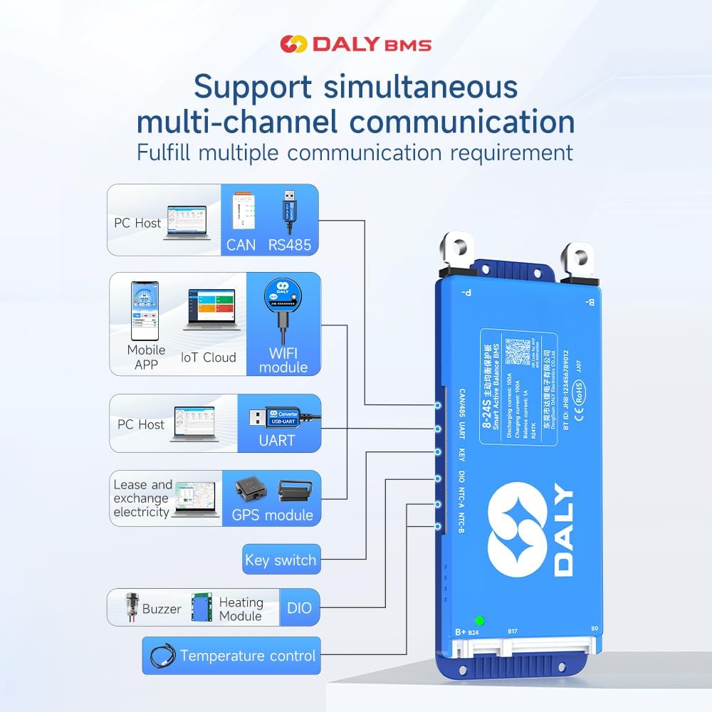
Figura 3.2: Oltreview of key features including cell count, current, balance, function, battery type, and communication.
4. Lista di imballaggio
Si prega di verificare che tutti gli articoli siano presenti nel pacco:
- Smart Active Balance BMS unit
- P-&B- Cable
- Screws (2 Pcs)
- SampCavo di ling
- B+ Cable
- NTC (Temperature Sensor - one standard, two optional)
- Manuale dell'utente (questo documento)
- Scatola di imballaggio
- RS485/CAN Port Cable

Figure 4.1: Visual representation of the DALY BMS and its included components.
5. Configurazione e installazione
Proper installation is critical for the safe and effective operation of your DALY BMS. It is imperative to follow the wiring sequence precisely.
5.1 Controlli pre-installazione
- Confirm your battery pack's cell count (8S-17S) and chemistry (Li-ion, LiFePO4, LTO) are compatible with this BMS model.
- Ensure all individual battery cells are balanced to a similar voltage prima di collegare il BMS.
- Verify that all cables and connectors are in good condition.
5.2 Istruzioni per il cablaggio
- Connect the B- wire: Connect the thick black B- wire from the BMS to the negative terminal of your battery pack.
- Connect the P- wire: Connect the thick black P- wire from the BMS to the negative terminal of your load/charger.
- Connect the B+ wire: Connect the thick red B+ wire from the BMS to the positive terminal of your battery pack.
- Collegare i cavi di bilanciamento: Carefully connect the balance wires (sampling cable) to each cell's positive terminal, starting from B0 (negative of the first cell) up to B17 (positive of the 17th cell), ensuring the correct sequence. Incorrect balance wire connection is a common cause of issues and can damage the BMS.
- Connect NTC (Temperature Sensor): Connect the NTC sensor to the designated port on the BMS and place the sensor on a battery cell to monitor temperature.
- Collegare i cavi di comunicazione: If using RS485 or CAN, connect the respective cables to the BMS and your communication device.
- Controllo finale: Ricontrollare tutte le connessioni prima di collegare l'alimentazione.
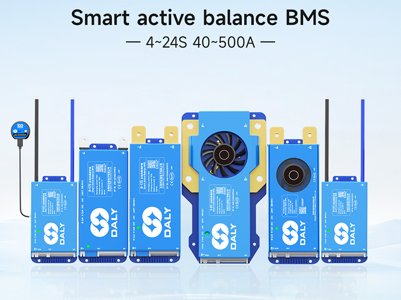
Figure 5.1: General wiring diagram for the DALY Smart Active Balance BMS. Ensure B- and P- are correctly identified and connected.

Figure 5.2: Illustration of the pre-charge connection for the BMS.

Figura 5.3: dettagliata view of connecting balance wires to individual battery cells.

Figura 5.4: Esample of connecting multiple BMS units in a parallel battery pack configuration.

Figure 5.5: Illustration of the B+ connection point on the battery pack.
6. Funzionamento
6.1 Mobile App Monitoring (Bluetooth)
The DALY Smart BMS features integrated Bluetooth for convenient monitoring via a mobile application.
- Download the "BalanceBMS" app from the iOS App Store or Android Play Store.
- Abilita il Bluetooth sul tuo dispositivo mobile.
- Open the app and search for your BMS device.
- Once connected, you can monitor real-time data such as individual cell voltages, volume totale della confezionetage, corrente, temperatura e stato di protezione.
- The app also allows for basic parameter adjustments and viewing of historical data.
6.2 Advanced Monitoring and Configuration (UART/RS485/CAN)
For advanced monitoring, data logging, and detailed parameter configuration, the BMS supports UART, RS485, and CAN communication interfaces. These typically require a dedicated adapter (e.g., USB-UART, WiFi module, or RS485/CAN adapter) and PC software or an IoT cloud platform.
- Connect the appropriate communication adapter to the BMS UART, RS485, or CAN port.
- Install the corresponding PC software or configure your IoT cloud platform.
- Refer to the specific adapter's manual for detailed connection and software usage instructions.

Figure 6.1: Diagram illustrating the various communication options and modules supported by the DALY BMS, including PC host, mobile app, IoT cloud, GPS, buzzer, and temperature control.
7. Manutenzione
The DALY Smart Active Balance BMS is designed for minimal maintenance. The active balancing feature continuously works to equalize cell voltages, which is crucial for the long-term health of your battery pack.
- Monitoraggio regolare: Periodically check the battery parameters via the mobile app or PC software to ensure normal operation.
- Ispezione visiva: Occasionally inspect all wiring and connections for any signs of wear, corrosion, or looseness.
- Pulizia: Keep the BMS unit clean and free from dust and debris to ensure proper heat dissipation.
8. Risoluzione Dei Problemi
If you encounter issues with your DALY Smart Active Balance BMS, refer to the following common problems and solutions:
| Problema | Possibile causa | Soluzione |
|---|---|---|
| BMS not powering on / No output | Incorrect wiring sequence; loose connections; BMS in protection mode. |
|
| Bluetooth connection issues / App not connecting | Bluetooth on phone disabled; app not updated; interference; BMS not active. |
|
| Cells not balancing properly | Volume cellulare iniziale significativotage difference; faulty balance wire connection. |
|
| BMS frequently enters protection mode | Sovracorrente, overvoltage, sottovoltage, or over-temperature condition. |
|
9. Specifiche
| Caratteristica | Dettaglio |
|---|---|
| Numero di modello | R24TM-150A |
| Conteggio celle supportato | 8S-17S |
| Tipi di batteria supportati | Li-ion, LiFePO4, LTO |
| Corrente di scarico | 150A |
| Corrente di carica | 150A |
| Corrente di equilibrio attivo | 1A |
| Interfacce di comunicazione | Bluetooth, RS485, CAN, UART |
| Dimensioni del prodotto (L x P x A) | 6.97 x 2.6 x 0.63 pollici (177 x 66 x 16 mm) |
| Peso dell'articolo | 9.7 once (275 grammi) |
| Produttore | Dongguan Daly Electronics Co., Ltd |

Figure 9.1: Table showing various DALY BMS models with their current ratings, sizes, and cable specifications. This model is 150A.
10. Scenari applicativi
The DALY Smart Active Balance BMS is suitable for a wide range of applications requiring reliable battery management:

Figura 10.1: Esamples of applications including electric two-wheelers, home energy storage, electric bicycles, electric tricycles, outdoor energy storage, electric wheelchairs, lead-acid to lithium upgrades, AGV, lease battery swapping, and RV energy storage.
11. Garanzia e supporto
Your DALY Smart Active Balance BMS comes with an 18-month warranty from the date of purchase, covering manufacturing defects. For technical assistance, troubleshooting, or warranty claims, please contact DALY customer service through your purchase platform or the official DALY websito.
Please have your model number (R24TM-150A) and purchase details ready when contacting support.