
1. Introduzione
The Matek Mateksys AP_PERIPH CAN-L4-BM is an ultra-precise digital power monitor designed for applications requiring accurate current and voltage measurements via the CAN bus. It utilizes the TI INA239 IC and runs ArduPilot AP_Periph firmware, supporting the CAN/DroneCAN protocol. This device provides reliable power monitoring without the need for calibration.
2 Caratteristiche
- Ultra-precise digital power monitoring.
- Based on TI INA239 and ArduPilot AP_Periph firmware.
- Supports CAN/DroneCAN protocol.
- No calibration required for accurate current and bus voltage letture.
- Low power loss due to 200µΩ typical conductive path resistance.
3. Specifiche
- MCU: STM32L431xC, 256KB Flash
- Power Monitor IC: INA239 (85-V, 16-Bit, High-Precision)
- Volume batteriatage Sense Input: 0~85 V
- Current Sense Range: 0~204.8A
- Load Current on Sensing Resistor: 150A (Continuous), 204.8A (Burst)
- Voltage Precisione: 0.1%
- Precisione attuale: 2%
- Interfaccia: CAN (DroneCAN Protocol), UART2 (spare, DFU), ST debug (SWCLK & SWDIO)
- Alimentazione elettrica: 4.5~5.5V @5V pad/pin
- Consumo energetico: 10mA
- Temperature di esercizio: Temperatura -40~85 °C
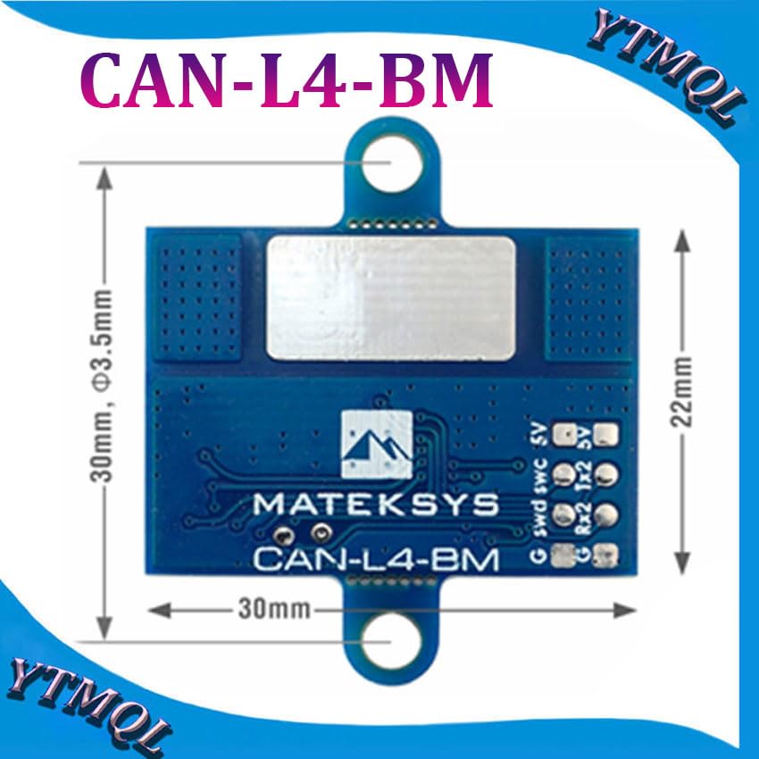
- Dimensioni della scheda: Dimensioni: 30 mm x 22 mm x 3 mm
- Peso: 4g
- Firmware: ArduPilot AP_Periph (Update via DroneCAN GUI Tool)
4. Prodotto finitoview
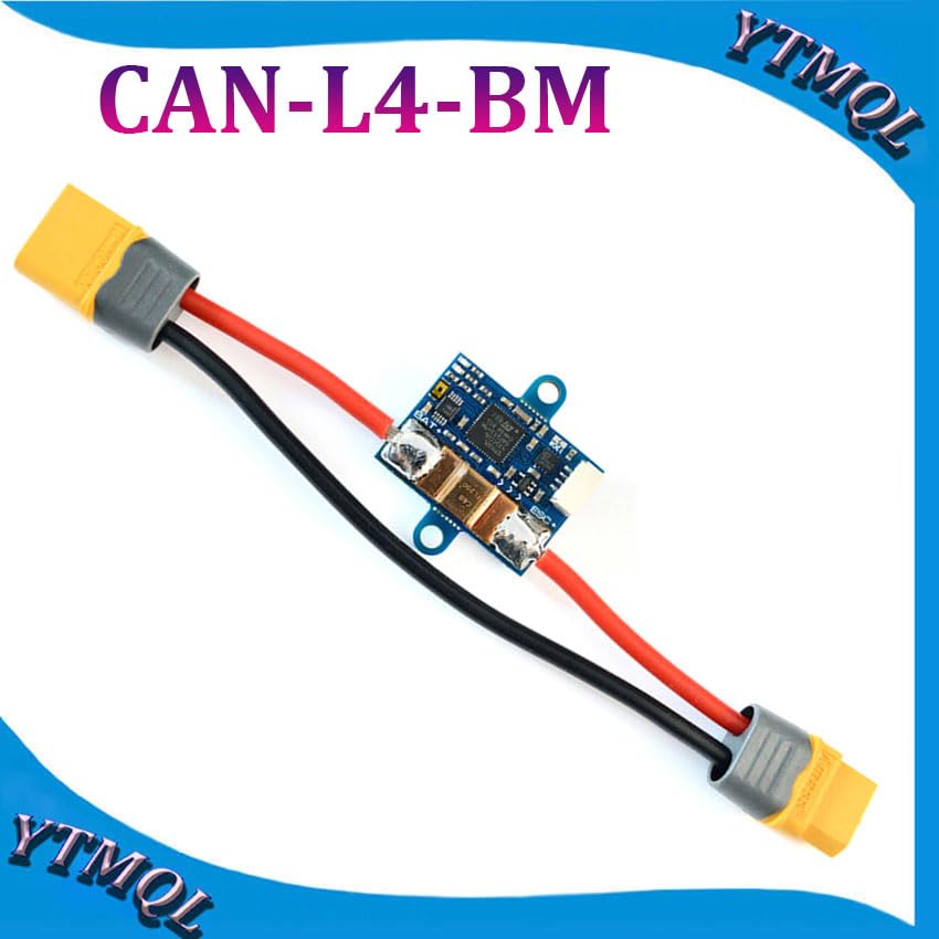
Disposizione dei componenti


5. Configurazione e installazione
Istruzioni di cablaggio
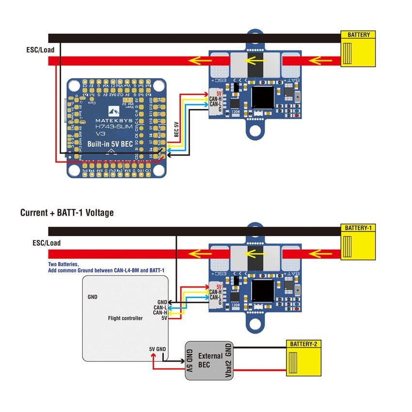
Proper wiring is crucial for accurate readings and safe operation of the CAN-L4-BM.

General Wiring Tips
- Solder the positive wires as close as possible to both sides of the current sensing resistor on the board for optimal accuracy.
- Ensure a common ground connection between the flight controller and the ESC/Load to prevent ground loops and ensure stable operation.
- If CAN wires are excessively long, bridge the 120R jumper on the CAN-L4-BM board to maintain signal integrity.
- The large pad on the bottom side of the board is a dead pad and has no circuit network; it can be used for structural support if needed.
- The two mounting ears can be carefully cut off if not required for installation in space-constrained environments.
Configurazione del firmware
The CAN-L4-BM runs ArduPilot AP_Periph firmware. Configuration is performed via the DroneCAN protocol through your flight controller's settings.
- Connect the CAN-L4-BM to your flight controller's CAN bus port.
- Set the appropriate parameter in your flight controller's firmware to enable the CAN driver:
- For CAN bus1:
CAN_P1_DRIVER = 1 - For CAN bus2:
CAN_P2_DRIVER = 1
- For CAN bus1:
- Configure battery monitoring by setting:
BATTx_MONITOR = 8(DroneCAN-BatteryInfo), where 'x' corresponds to the battery monitor instance you are configuring. - Firmware updates for the CAN-L4-BM can be performed using the DroneCAN GUI Tool.
6. Funzionamento
Indicatori LED
- Blue LED (Fast blinking): Indicates the board is in the process of booting up.
- Blue LED (Slow blinking): Indicates the board is working correctly and communicating via CAN.
- LED rosso: Indicates that 3.3V power is present on the board.
Monitoraggio dei dati
Once properly configured and powered, the flight controller will receive accurate current and bus voltage data from the CAN-L4-BM via the DroneCAN bus. This data can be logged and monitored through your flight controller's telemetry system or compatible ground station software.
7. Manutenzione e buone pratiche
- Regularly inspect all soldered connections for integrity and signs of wear or corrosion.
- Keep the board free from dust, moisture, and debris to ensure optimal performance and longevity.
- Ensure proper ventilation if operating the device in enclosed spaces, although the CAN-L4-BM has a wide operating temperature range.
- Avoid exposing the board to extreme environmental conditions (e.g., excessive humidity, direct water contact) beyond its specified operating range.
8. Risoluzione Dei Problemi
Problemi comuni
- No data from monitor:
- Verify all CAN bus connections (CAN-H, CAN-L, GND, 5V) are secure and correct.
- Check the LED indicators for proper boot and operation (a slow blue blink indicates normal function).
- Garantire
CAN_P1_DRIVERorCAN_P2_DRIVERis set correctly in the flight controller parameters. - Conferma che
BATTx_MONITOR = 8is set for the correct battery monitor instance. - Check for any short circuits or incorrect voltage supply to the CAN-L4-BM board.
- Letture imprecise:
- Ensure positive wires are soldered as close as possible to the current sensing resistor on the board.
- Verify common ground connections between all components in the power system.
- Check for any physical damage to the board or its components that might affect sensor accuracy.
- La scheda non si accende:
- Confirm that a stable 4.5~5.5V supply is provided to the 5V pad/pin.
- Check the Red 3.3V indicator LED; if it's off, there might be a power issue.
- Inspect all power supply wiring for breaks or incorrect connections.
9. Contatto e supporto
For further assistance, technical support, or to access additional resources, please refer to the official Mateksys documentation available on their website or consult relevant community forums for ArduPilot and DroneCAN users.