1. Introduzione
The Generic BM4070 LCD Digital Multimeter is a high-precision LCR tester designed for accurate electrical measurements in both field and laboratory settings. It features a clear LCD display for easy data reading, fast response times, and a compact, lightweight design for portability. This device is equipped with multiple functions for professional electrical testing, making it suitable for a wide range of applications.
2. Informazioni sulla sicurezza
WARNING: To avoid electric shock, do not touch the meter's probes or exposed circuits during measurement. Always ensure the device is properly configured for the measurement type before connecting to a circuit. Do not attempt to measure voltagcorrenti o correnti che superano i limiti specificati del dispositivo.
- Always inspect the test leads for damage before use.
- Assicurarsi che la batteria sia installata correttamente e che abbia una carica sufficiente.
- Non utilizzare il misuratore in ambienti umidi o con le mani bagnate.
- Refer to the specifications section for maximum input values.
3. Prodotto finitoview
The BM4070 Digital Multimeter is designed for ease of use and clear readings. Below is an illustration of the device and its key components.
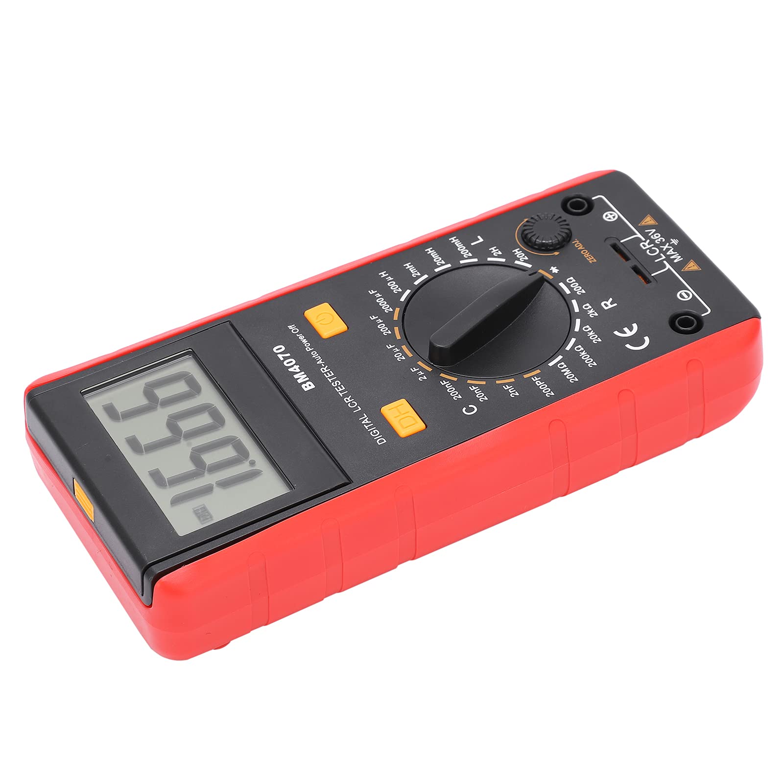
Figura 1: Fronte view of the Generic BM4070 LCD Digital Multimeter, showing the LCD display, rotary switch, and function buttons.

Figure 2: Close-up of the BM4070's high-definition LCD display, showing a clear numerical reading.
Componenti chiave:
- Schermo LCD: Mostra le letture delle misurazioni e gli indicatori.
- Interruttore rotante: Used to select measurement functions (Capacitance C, Inductance L, Resistance R) and ranges.
- DH Button: Funzione Data Hold per congelare la lettura corrente sul display.
- Pulsante di accensione: Accende o spegne il dispositivo.
- Jack di ingresso: Collegare i puntali di prova per le misurazioni.
- ZERO ADJ. Knob: For zero adjustment, typically used for resistance measurements to compensate for lead resistance.

Figure 3: Bottom section of the multimeter showing the input jacks and the LCR MAX 36V safety marking.
4. Impostazione
4.1 Installazione della batteria
- Individuare il vano batteria sul retro del multimetro.
- Using a screwdriver, carefully open the battery cover.
- Insert one 9V 6F22 battery, ensuring correct polarity. (Battery not included)
- Riposizionare il coperchio della batteria e fissarlo con la vite.
4.2 Collegamento dei puntali di prova
- Assicurarsi che il multimetro sia spento.
- Insert the black test lead into the common (COM) input jack.
- Insert the red test lead into the appropriate input jack for your measurement (e.g., for LCR measurements, use the designated LCR input).
5. Istruzioni per l'uso
5.1 Accensione/spegnimento
Premere il tasto Pulsante di accensione (usually marked with a circle and a vertical line) to turn the multimeter on. Press it again to turn the device off.
5.2 Selezione della funzione di misurazione
Ruotare la parte centrale Interruttore rotante to select the desired measurement function (C for Capacitance, L for Inductance, R for Resistance) and the appropriate range. Start with a higher range if the value is unknown to prevent overloading.
5.3 Esecuzione delle misurazioni
- After selecting the function and range, connect the test leads to the component you wish to measure.
- For resistance measurements, you may need to use the ZERO ADJ. knob to zero out the resistance of the test leads before connecting to the component.
- Leggere il valore di misurazione visualizzato sullo schermo LCD.
5.4 Funzione di conservazione dei dati
Premere il tasto DH Button to freeze the current reading on the display. Press it again to release the hold function and resume live readings.
6. Manutenzione
- Mantenere il multimetro pulito e asciutto. Utilizzare un panno morbido e asciutto.amp panno per la pulizia; non utilizzare detergenti abrasivi o solventi.
- Conservare il dispositivo in un luogo fresco e asciutto, lontano dalla luce solare diretta e da temperature estreme.
- Se il dispositivo non verrà utilizzato per un periodo prolungato, rimuovere la batteria per evitare perdite.
- Regularly check the test leads for any signs of wear or damage. Replace them if necessary.
7. Risoluzione Dei Problemi
If you encounter issues with your BM4070 multimeter, refer to the following common problems and solutions:
- Il dispositivo non si accende: Verificare che la batteria sia installata correttamente e abbia una carica sufficiente. Sostituire la batteria se necessario.
- Nessuna lettura o 'OL' visualizzato: Ensure the test leads are properly connected to the component and the correct measurement function and range are selected. 'OL' (Overload) indicates the measured value exceeds the selected range; switch to a higher range.
- Letture imprecise: Check for proper test lead connection. Ensure the ZERO ADJ. knob is correctly set for resistance measurements. Verify the component is functioning correctly.
Se il problema persiste, contatta l'assistenza clienti.
8. Specifiche
| Caratteristica | Specificazione |
|---|---|
| Tipo di articolo | Multimetro |
| Modello | BM4070 |
| Materiale | addominali |
| Alimentazione elettrica | 1x9V 6F22 Battery (not included) |
| Samptasso di ling | 3 volta al secondo |
| Ambiente operativo | da 0℃ a 40℃ |
| Ambiente di archiviazione | -10℃ a 50℃ |
| Precisione della misurazione | 0.1mm (General) |
| Intervallo di capacità | 200pF ~ 200μF (±2.5%+5), 2000μF (±5.0%+5) |
| Gamma di induttanza | 200uH (±3.0%+5), 2mH ~ 2H (±2%+5), 20H (±5%+5) |
| Basso volumetage Visualizza | Battery symbol indication |
9. Contenuto della confezione
Nella confezione del prodotto sono inclusi i seguenti articoli:

Figure 4: Contents of the BM4070 package, including the multimeter, test clips, manual, and tool bag.
- Multimeter x 1 (Battery not included)
- Test Clips x 2
- Manuale di istruzioni x 1
- Borsa degli attrezzi x 1
10. Garanzia e supporto
Specific warranty and support information is not provided in the product details. Please refer to the retailer or manufacturer's website for details regarding warranty coverage and customer support options.

