1. Introduzione
This manual provides essential information for the installation, operation, and maintenance of your STEPPERONLINE Closed Loop Stepper Motor Kit. This kit includes a CL57Y-V20 Closed Loop Stepper Driver, a 23HS40-5004D-E1K-1M5 Nema 23 Closed Loop Stepper Motor, and an RS232 debugging cable (CABLE-PC-2).
The closed-loop system offers high speed, high torque, high precision, and eliminates step loss, making it suitable for applications such as 3D printers, CNC machines, carving machines, dispensers, and other automation systems.

Figura 1: Oltreview of the STEPPERONLINE Closed Loop Stepper Motor Kit, including the driver, motor, and cables.
2. Configurazione e installazione
2.1 Componenti del kit
- 1 x CL57Y-V20 Y Series V2.0 Closed Loop Stepper Driver (0-7.0A, 24-50VDC)
- 1 x 23HS40-5004D-E1K-1M5 S Series Nema 23 Closed Loop Stepper Motor (3.00Nm, Encoder 1000PPR)
- 1 x CABLE-PC-2 RS232 Debugging Cable
2.2 Driver Overview (CL57Y-V20)
The CL57Y-V20 driver is designed for Nema 17, 23, and 24 stepper motors. It features a 5V/24V selector for control signal voltage, with a factory setting of 24V. This version offers stable recognition of 3.3V signals, similar to Arduino, and improved performance at high speeds.
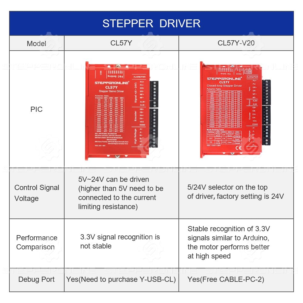
Figura 2: Fronte view of the CL57Y-V20 Closed Loop Stepper Driver, showing input/output terminals and DIP switches.
2.3 Motor Overview (23HS40-5004D-E1K-1M5)
The 23HS40-5004D-E1K-1M5 is a Nema 23 bipolar stepper motor with a 1.8-degree step angle and 3.00Nm holding torque. It integrates a 1000PPR (4000CPR) optical incremental encoder for precise feedback.

Figura 3: Fronte view of the Nema 23 Closed Loop Stepper Motor with integrated encoder and shaft.
2.4 Collegamenti di cablaggio
Proper wiring is crucial for the correct operation of the closed-loop system. Refer to the following tables and images for motor and encoder connections.

Figure 4: Motor and encoder wiring cables with color-coded leads.
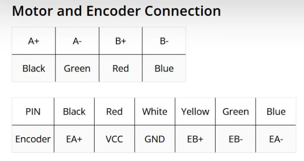
Figure 5: Detailed table showing the color-coded connections for the motor and encoder to the driver terminals.
Collegamento del motore:
- A+: Black wire
- A-: Green wire
- B+: Red wire
- B-: Blue wire
Collegamento dell'encoder:
- EA+: Black wire
- VCC: Red wire
- GND: White wire
- EB+: Yellow wire
- EB-: Green wire
- EA-: Blue wire
Ensure all connections are secure and correctly matched to prevent damage to the components.
2.5 Collegamento dell'alimentazione
Connect a DC power supply within the range of +24V to +50VDC (typical 36VDC) to the driver's power input terminals (V+ and V-). Observe polarity carefully.
2.6 Collegamento del segnale di controllo
Connect your pulse and direction signals (PU+, PU-, DR+, DR-) from your controller to the driver. The logic signal current is typically 10mA. The driver supports pulse input frequencies up to 200kHz.
3. Istruzioni per l'uso
3.1 Microstep Settings
The CL57Y-V20 driver allows for microstep adjustments using DIP switches. The microstep range is from 400 to 40000 steps per revolution, enabling very accurate operation. Refer to the driver's labeling or specific documentation for detailed DIP switch configurations for desired microstep resolutions.
3.2 Debugging Cable (CABLE-PC-2)
The included CABLE-PC-2 RS232 debugging cable can be used to connect the driver to a computer for advanced configuration and monitoring. This allows for fine-tuning parameters and accessing diagnostic features.

Figure 6: The CABLE-PC-2 RS232 debugging cable for driver configuration.
3.3 Accensione iniziale
After ensuring all connections are correct, apply power to the driver. The motor should engage and hold its position. If the motor feels stiff or resists manual rotation when powered, this is normal behavior for a stepper motor holding its position.
3.4 Operation with Controller
Send pulse and direction signals from your CNC controller or microcontroller. The closed-loop system will monitor the motor's position via the encoder and adjust current to ensure no steps are lost, providing precise and reliable motion.
4. Manutenzione
- Ispezione regolare: Controllare periodicamente tutti i collegamenti elettrici per verificarne la tenuta e l'eventuale presenza di segni di usura o danni.
- Pulizia: Keep the motor and driver free from dust, debris, and moisture. Use a soft, dry cloth for cleaning. Avoid using solvents or harsh chemicals.
- Condizioni ambientali: Ensure the operating environment is within the specified temperature and humidity ranges to prevent overheating or condensation.
- Dissipazione del calore: Ensure adequate airflow around the driver, especially during continuous operation, to prevent overheating. Consider mounting the driver on a metal surface for better heat dissipation if necessary.
5. Risoluzione Dei Problemi
- Motor Not Moving or Stalling:
- Controllare l'alimentazione voltagee capacità attuale.
- Verify motor and encoder wiring connections are correct and secure.
- Ensure control signals (pulse/direction) are being sent correctly from the controller.
- Reduce acceleration/deceleration settings or increase current limits if the motor is stalling under load.
- Motor Vibrates but Does Not Rotate:
- Check for incorrect motor phase wiring. Refer to the wiring diagram.
- Ensure the motor is not mechanically bound or overloaded.
- Driver Overheating:
- Assicurare un'adeguata ventilazione attorno al conducente.
- Check if the motor current setting is too high for the application.
- Verificare il vol dell'alimentatoretage rientra nell'intervallo specificato.
- Communication Issues with Debugging Cable:
- Ensure the correct software and drivers are installed for the RS232 cable.
- Verify the COM port settings on your computer match the cable connection.
- Motor is Hard to Turn When Connected (Normal Behavior):
- When the motor is powered and holding position, it will naturally resist manual rotation. This indicates the driver is actively controlling the motor.
6. Specifiche
6.1 Motor Specifications (23HS40-5004D-E1K-1M5)
- Tipo di motore: Bipolar Stepper
- Angolo di passo: 1.8 gradi
- Holding Torque: 3.00 Nm (424.83 oz.in)
- Rated Current/Phase: 5.0A
- Phase Resistance: 0.7 ohm ± 10%
- Induttanza: 2.3 mH ± 20% (1KHz)
- Classe di isolamento: B 130°C [266°F]
- Dimensioni della cornice: 57 x 57 millimetri
- Lunghezza di corpo: 122 millimetri
- Diametro dell'albero: Diametro 8 mm
- Lunghezza dell'albero: 22 millimetri
- D-Cut Length: 15 millimetri
- Lunghezza del cavo: 1500 millimetri
- Tipo di codificatore: Optical Incremental
- Risoluzione dell'encoder: 1000 PPR (4000 CPR)
- Encoder Output Signal Channels: 2 canali
- Volume di alimentazione dell'encodertage: 4V - 5V
6.2 Driver Specifications (CL57Y-V20)
- Output Peak Current: 0~7A (0~5 RMS)
- Ingresso volumetage: +24~50VDC (Typical 36VDC)
- Logic Signal Current: 7~16mA (Typical 10mA)
- Pulse Input Frequency: 0 ~ 200 kHz
- Larghezza di impulso: 2.5μS
- Resistenza di isolamento: 500 MΩ
- Microsteps: 400 - 40000
6.3 Informazioni generali sul prodotto
- Marca: STEPPERONLINE
- Peso dell'articolo: 4.95 libbre
- Dimensioni della confezione: 11.14 x 10.55 x 5.67 pollici
7. Garanzia e supporto
For warranty information and technical support, please refer to the official STEPPERONLINE websito o contattare direttamente il servizio clienti. Conservare la ricevuta d'acquisto per eventuali reclami in garanzia.
Puoi visitare il STEPPERONLINE Store on Amazon per ulteriori risorse e informazioni sui prodotti.
8. Video del prodotto
Guarda questo video per una panoramica visivaview or demonstration of the product.
Video: A demonstration or overview of the STEPPERONLINE Closed Loop Stepper Motor Kit.