1. Introduzione
This manual provides instructions for the safe and effective use of the Sealey MM19 Digital Multimeter. The MM19 is a general-purpose multimeter designed for measuring various electrical parameters, including AC and DC voltage, DC current, resistance, audible continuity, and diode/transistor verification. Please read this manual thoroughly before operation and retain it for future reference.
2. Informazioni sulla sicurezza
Always observe basic safety precautions when using electrical test equipment to reduce the risk of fire, electric shock, or personal injury. This device complies with IEC 1010 and CE CAT II safety standards.
- Non superare i limiti massimi di input for any function. Refer to the specifications section for details.
- Non applicare mai voltage to the meter when the rotary switch is set to Resistance (Ω), Diode, Continuity, or Current (A) functions.
- Prestare attenzione quando si lavora con voltagoltre 30 V CA RMS, 42 V picco o 60 V CC. Questi voltagrappresentano un rischio di scossa elettrica.
- Assicurarsi che i cavi di prova siano in buone condizioni, without cracked or broken insulation.
- Always connect the common (COM) test lead first and disconnect it last.
- Disconnect power to the circuit under test before measuring resistance or continuity.
- Sostituire immediatamente la batteria quando appare l'indicatore di batteria scarica per garantire letture accurate.
3. Prodotto finitoview
The Sealey MM19 Digital Multimeter features a clear LCD display, a central rotary switch for function selection, and input jacks for test leads.
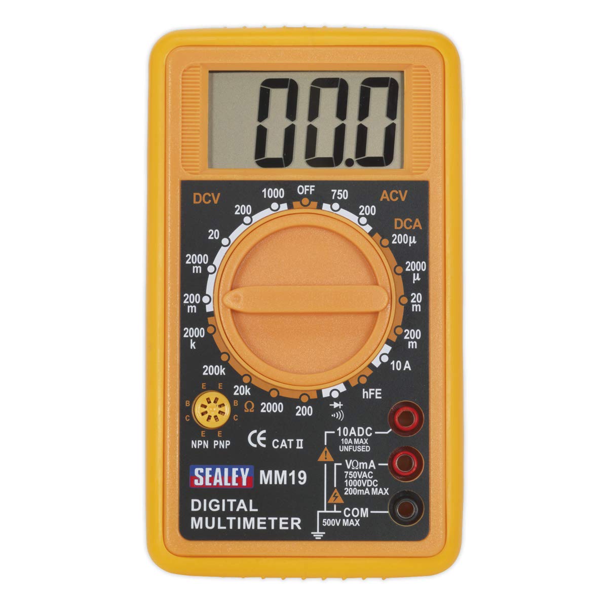
The Sealey MM19 Digital Multimeter, shown with its yellow casing, large LCD display, rotary function switch, and red and black test leads connected to the input jacks.
Componenti:
- Schermo LCD: Large (46 x 25mm) digital display for reading measurements.
- Interruttore rotante: Utilizzato per selezionare la funzione e l'intervallo di misurazione desiderati.
- Jack di ingresso VΩmA: Per volumetage, resistance, and current measurements up to 200mA.
- 10ADC Input Jack: For high current measurements up to 10A DC (unfused).
- Jack di ingresso COM: Input comune (negativo) per tutte le misurazioni.
- Presa hFE: For transistor (NPN/PNP) testing.
- Puntali di prova: Red (positive) and Black (negative) leads for connecting to circuits.
4. Impostazione
4.1. Installazione della batteria
The Sealey MM19 Multimeter requires a 9V battery for operation. If the display does not illuminate or shows a low battery indicator, the battery needs to be installed or replaced.
- Assicurarsi che il multimetro sia spento.
- Individuare il coperchio del vano batterie sul retro dell'unità.
- Rimuovere la/le vite/i che fissano il coperchio e sollevarlo con cautela.
- Collegare una nuova batteria da 9 V ai morsetti della batteria, rispettando la polarità corretta.
- Inserire la batteria all'interno del vano e riposizionare il coperchio, fissandolo con la/le vite/i.
4.2. Collegamento dei puntali di prova
The multimeter is supplied with a pair of test leads (red and black).
- Inserire il puntale di prova nero dentro il COM Jack di ingresso (comune).
- Per la maggior parte delle misurazioni (voltage, resistance, low current), insert the puntale di prova rosso dentro il VΩmA presa di ingresso.
- For high DC current measurements (up to 10A), insert the puntale di prova rosso dentro il 10Adc presa di ingresso.
5. Istruzioni per l'uso
To operate the multimeter, select the desired function and range using the rotary switch.
5.1 Misurazione del volume CCtage(DCV)
- Insert the red lead into the VΩmA jack and the black lead into the COM jack.
- Set the rotary switch to the desired DCV range (e.g., 200m, 2000m, 20, 200, 1000). Start with the highest range if the voltage è sconosciuto.
- Collegare i puntali di prova al componente o al circuito da misurare.
- Leggi il vol.tage valore sul display LCD.
5.2. Misurazione del volume CAtage(ACV)
- Insert the red lead into the VΩmA jack and the black lead into the COM jack.
- Set the rotary switch to the desired ACV range (e.g., 200, 750). Start with the highest range if the voltage è sconosciuto.
- Collegare i puntali di prova al componente o al circuito da misurare.
- Leggi il vol.tage valore sul display LCD.
5.3. Misurazione della corrente continua (DCA)
- Per correnti fino a 200 mA: Insert the red lead into the VΩmA jack and the black lead into the COM jack.
- Per correnti fino a 10A: Insert the red lead into the 10ADC jack and the black lead into the COM jack.
- Set the rotary switch to the desired DCA range (e.g., 200μ, 2000μ, 20m, 200m, 10A). Start with the highest range if the current is unknown.
- Togliere l'alimentazione al circuito. Open the circuit where the current is to be measured.
- Collegare il multimetro in serie al circuito.
- Alimentare il circuito e leggere il valore corrente sul display LCD.
5.4. Misurazione della resistenza (Ω)
- Insert the red lead into the VΩmA jack and the black lead into the COM jack.
- Set the rotary switch to the desired Resistance (Ω) range (e.g., 200, 2000, 20k, 200k, 2000k).
- Assicurarsi che il circuito sottoposto a test sia disattivato.
- Collegare i puntali di prova al componente da misurare.
- Leggere il valore della resistenza sul display LCD.
5.5. Test di continuità udibile
- Insert the red lead into the VΩmA jack and the black lead into the COM jack.
- Set the rotary switch to the continuity symbol (speaker icon).
- Assicurarsi che il circuito sottoposto a test sia disattivato.
- Collegare i puntali di prova al componente o al filo.
- If continuity exists (low resistance), the meter will emit an audible tone. The display will show the resistance value.
5.6. Diode/Transistor Verification Mode (hFE)
- Insert the red lead into the VΩmA jack and the black lead into the COM jack for diode testing.
- Set the rotary switch to the diode symbol.
- Collegare il puntale rosso all'anodo e il puntale nero al catodo del diodo. Il display mostrerà la tensione diretta.tage caduta. Invertire i cavi; il display dovrebbe visualizzare 'OL' (circuito aperto) per un diodo funzionante.
- For transistor hFE measurement, insert the transistor leads (Emitter, Base, Collector) into the appropriate sockets (E, B, C) in the hFE test socket, ensuring correct NPN or PNP type selection.
- Leggere il valore hFE sul display LCD.
6. Manutenzione
6.1. Pulizia
Pulisci il contatore casing con annuncioamp panno e un detergente delicato. Non utilizzare abrasivi o solventi. Assicurarsi che il misuratore sia completamente asciutto prima dell'uso.
6.2. Sostituzione della batteria
Refer to Section 4.1 for battery installation instructions. Replace the 9V battery when the low battery indicator appears on the display to maintain measurement accuracy.
7. Risoluzione Dei Problemi
- Nessuna visualizzazione: Controllare l'installazione della batteria e assicurarsi che sia sufficientemente carica.
- 'OL' o '1' sul display: This usually indicates an over-range condition or an open circuit. Select a higher range or check connections.
- Letture errate: Ensure the correct function and range are selected. Check test lead connections and battery condition.
- No Continuity Tone: Verify the circuit is de-energized and the leads are making good contact.
8. Specifiche
| Parametro | Valore |
|---|---|
| Marca | Marea |
| Numero di modello | MM19 |
| Fonte di alimentazione | Alimentato a batteria (9 V) |
| Display | Digital LCD (46 x 25mm) |
| Volume DCtage(DCV) | 200 mV, 2000 mV, 20 V, 200 V, 1000 V |
| Volume ACtage(ACV) | 200V, 750V |
| Corrente CC (DCA) | 200µA, 2000µA, 20mA, 200mA, 10A |
| Resistenza (Ω) | 200Ω, 2000Ω, 20kΩ, 200kΩ, 2000kΩ |
| Continuità | Audible tone below approx. 30Ω |
| Test diodi | Volume in avantitage display a goccia |
| Test transistor | hFE (NPN/PNP) |
| Valutazione di sicurezza | CE CAT II, IEC 1010 |
| Dimensioni (L x P x A) | 1.93 x 4.21 x 6.06 pollici |
| Peso dell'articolo | 9.5 once (0.27 chilogrammi) |
9. Garanzia e supporto
For warranty information or technical support, please refer to the documentation provided with your purchase or contact Sealey customer service directly. Keep your proof of purchase for any warranty claims.


