1. Introduzione
The Velleman DVM810 is a compact and economical 3 1/2 digit digital multimeter designed for measuring DC and AC voltages, DC currents, resistance, and for performing diode and transistor (hFE) tests. It features overload protection and automatic polarity indication, making it suitable for hobbyists, field use, and workshops. This manual provides essential information for the safe and effective operation of your DVM810 multimeter.
2. Caratteristiche del prodotto
- Indicazione automatica della polarità
- Voltage measurements: AC 500V and DC 500V maximum
- Current measurements: DC 10A maximum (0.2A fused, 10A unfused)
- Resistance measurements: Up to 2MΩ
- Diode and transistor (hFE) test functions
- Protezione da sovraccarico
- Compact design with 3 1/2 digit LCD display
3. Contenuto della confezione
Si prega di controllare il contenuto della confezione per assicurarsi che siano presenti tutti gli articoli:
- Multimetro digitale Velleman DVM810
- Cavi di prova (uno rosso, uno nero)
- Manuale di istruzioni
4. Informazioni importanti sulla sicurezza
Leggere attentamente tutte le avvertenze e le istruzioni di sicurezza prima di utilizzare questo prodotto. Il mancato rispetto di queste istruzioni può causare scosse elettriche, incendi o lesioni gravi.
- Prima di effettuare qualsiasi misurazione, assicurarsi sempre che il multimetro sia impostato sulla funzione e sull'intervallo corretti.
- Never exceed the maximum input limits for any range. The maximum voltage for AC/DC is 500V.
- Do not attempt to measure current on circuits with voltages superiore a 250V.
- Inspect test leads for damaged insulation or exposed metal before each use. Replace damaged leads immediately.
- Non utilizzare il multimetro se appare danneggiato o se la custodia è aperta.
- Exercise extreme caution when working with live circuits. Use appropriate personal protective equipment.
- Scollegare sempre l'alimentazione dal circuito e scaricare l'alto volumetage capacitors before measuring resistance or performing diode/transistor tests.
- Replace the battery when the low battery indicator appears on the display to ensure accurate readings.
5. Prodotto finitoview
Familiarize yourself with the components of your Velleman DVM810 multimeter:
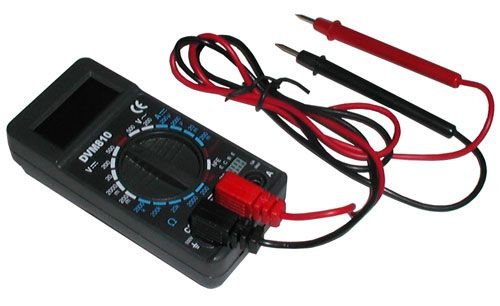
Figure 1: Velleman DVM810 Digital Multimeter. This image displays the front view of the compact multimeter, highlighting its liquid crystal display (LCD), the central rotary function switch, and the input jacks for test leads at the bottom.
- Schermo LCD: Shows measurement readings, units, and polarity.
- Interruttore rotante: Utilizzato per selezionare la funzione e l'intervallo di misurazione desiderati.
- Jack di ingresso:
- Jack COM: Common (negative) input for all measurements. Connect the black test lead here.
- Presa VΩmA: Input positivo per voltage, resistance, and current measurements up to 200mA. Connect the red test lead here.
- Presa 10A: Positive input for high current measurements (up to 10A). Connect the red test lead here for 10A measurements.
- Puntali di prova: Red and black leads used to connect the multimeter to the circuit under test.
6. Impostazione
6.1 Installazione della batteria
The DVM810 multimeter requires a 9V battery (not always included). To install or replace the battery:
- Ensure the multimeter is turned OFF (rotary switch set to OFF).
- Individuare il coperchio del vano batterie sul retro dell'unità.
- Rimuovere la/le vite/i che fissano il coperchio e sollevarlo con cautela.
- Collegare una nuova batteria da 9 V al morsetto della batteria, rispettando la polarità corretta.
- Inserire la batteria nel vano e riposizionare il coperchio, fissandolo con la/le vite/i.
6.2 Collegamento dei puntali di prova
Per misurazioni precise e sicure, collegare sempre correttamente i puntali di prova:
- Inserire il puntale nero nel COM (comune) jack.
- Per la maggior parte delle misurazioni (voltage, resistance, diode, hFE, and current up to 200mA), insert the red test lead into the VΩmA cricco.
- Per misurazioni di corrente elevata (fino a 10 A), inserire il puntale di prova rosso nel 10A cricco.
7. Istruzioni per l'uso
Before making any measurement, ensure the test leads are correctly connected and the rotary switch is set to the appropriate function and range.
7.1 Misurazione del volume CCtage (V=)
- Inserire il cavo rosso nel VΩmA jack and the black lead into the COM cricco.
- Impostare il selettore rotativo sul volume CC desideratotage (V=) range. Start with the highest range if the voltage è sconosciuto.
- Connect the test leads across the component or circuit to be measured (in parallel).
- Leggi il vol.tage value on the LCD display. The display will show the correct polarity.
7.2 Misurazione del volume CAtage(V~)
- Inserire il cavo rosso nel VΩmA jack and the black lead into the COM cricco.
- Impostare il selettore rotativo sul volume CA desideratotage (V~) range. Start with the highest range if the voltage è sconosciuto.
- Connect the test leads across the component or circuit to be measured (in parallel).
- Leggi il vol.tage valore sul display LCD.
7.3 Misurazione della corrente continua (A=)
Attenzione: non collegare mai il multimetro in parallelo con un voltmetrotage sorgente quando si misura la corrente, poiché ciò potrebbe far saltare il fusibile o danneggiare il misuratore.
- Determine the expected current. For currents up to 200mA, insert the red lead into the VΩmA jack. For currents up to 10A, insert the red lead into the 10A jack. Always insert the black lead into the COM cricco.
- Set the rotary switch to the appropriate DC Current (A=) range. Start with the highest range if the current is unknown.
- Turn off power to the circuit. Open the circuit where the current is to be measured.
- Collegare il multimetro in serie al circuito.
- Restore power to the circuit and read the current value on the LCD display.
7.4 Misurazione della resistenza (Ω)
Caution: Ensure the circuit is completely de-energized and all capacitors are discharged before measuring resistance.
- Inserire il cavo rosso nel VΩmA jack and the black lead into the COM cricco.
- Impostare il selettore rotativo sull'intervallo di resistenza (Ω) desiderato. Iniziare con un intervallo più alto se la resistenza è sconosciuta.
- Collegare i puntali di prova al componente da misurare.
- Leggere il valore della resistenza sul display LCD.
7.5 Test diodi
Caution: Ensure the diode is disconnected from the circuit or the circuit is de-energized before testing.
- Inserire il cavo rosso nel VΩmA jack and the black lead into the COM cricco.
- Set the rotary switch to the Diode symbol (→|).
- Collegare il puntale rosso all'anodo e il puntale nero al catodo del diodo. Il display mostrerà la tensione diretta.tagcaduta di tensione (tipicamente da 0.5 V a 0.8 V per i diodi al silicio).
- Reverse the leads. The display should show 'OL' (Overload) for a good diode. If it shows a reading in both directions or 'OL' in both directions, the diode may be faulty.
7.6 Test del transistor (hFE)
Caution: Ensure the transistor is disconnected from the circuit before testing.
- Inserire il cavo rosso nel VΩmA jack and the black lead into the COM cricco.
- Portare il selettore in posizione hFE.
- Identify if the transistor is NPN or PNP. Insert the transistor's emitter, base, and collector leads into the corresponding holes in the hFE socket on the multimeter.
- Leggere il valore hFE (guadagno di corrente CC) sul display LCD.
8. Specifiche
| Parametro | Valore |
|---|---|
| Marca | Velleman |
| Numero di modello | DVM810 |
| Tipo di misurazione | Multimetro |
| Volume DCtage Gamma | Fino a 500V |
| Volume ACtage Gamma | Fino a 500V |
| Intervallo di corrente CC | Up to 10A (0.2A fused, 10A unfused) |
| Intervallo di resistenza | Fino a 2 MΩ |
| Test diodi | SÌ |
| Test del transistor (hFE) | SÌ |
| Display | 3 1/2 Digit LCD |
| Fonte di alimentazione | Batteria da 9 V (non inclusa) |
| Dimensioni | Circa 3.70" x 1.81" x 1.03" |
| Peso dell'articolo | Circa 3.2 once (0.2 libbre) |
| Codice UPC | 836479002272 |
9. Manutenzione
9.1 Sostituzione della batteria
When the low battery indicator appears on the LCD, replace the 9V battery as described in Section 6.1. A weak battery can lead to inaccurate readings.
9.2 Pulizia
Per pulire il multimetro, pulire la custodia con un pannoamp cloth and a mild detergent. Do not use abrasives or solvents. Ensure the unit is completely dry before use.
9.3 Ispezione del cavo di prova
Regularly inspect the test leads for any signs of damage, such as cracked insulation, exposed wires, or loose connections. Replace damaged leads immediately to prevent electric shock hazards.
10. Risoluzione Dei Problemi
- Nessun display o display debole: Controllare la batteria. Sostituirla se necessario.
- Letture errate:
- Assicurarsi che il selettore rotativo sia impostato sulla funzione e sull'intervallo corretti.
- Controllare il volume della batteriatage; replace if low.
- Assicurarsi che i puntali di prova siano collegati correttamente e non danneggiati.
- Per le misurazioni della resistenza, assicurarsi che il circuito sia disattivato.
- 'OL' (sovraccarico) visualizzato: Il valore misurato supera l'intervallo selezionato. Selezionare un intervallo più alto o assicurarsi che il circuito rientri nelle capacità del misuratore.
- Fusibile bruciato (durante la misurazione della corrente): If the meter stops measuring current, the internal fuse may have blown. Refer to a qualified technician for fuse replacement.
11. Garanzia e supporto
Warranty information for the Velleman DVM810 Digital Multimeter is typically provided with your purchase documentation or can be found on the official Velleman website. For technical support, service, or further inquiries, please refer to the contact information provided by your retailer or the manufacturer's official support channels.


