1. Introduzione
This manual provides instructions for the safe and effective operation of the Voltcraft VC155 Digital Hand-held Multimeter. The VC155 is designed for measuring and displaying electrical parameters within the CAT III 600V category. It offers functions for measuring direct and alternating voltage, resistance, acoustic continuity, diode testing, non-contact 230V/AC voltage testing, electric current (10A, mA, µA), and K-type temperature measurement.
Please read this manual thoroughly before using the device to ensure proper handling and to prevent potential hazards.
2. Informazioni sulla sicurezza
Observe all safety precautions to prevent electric shock, injury, or damage to the meter or the equipment under test.
- The device is rated for Measurement Category CAT III 600V. Do not exceed these limits.
- Always ensure the test leads are in good condition and properly connected before making measurements.
- Non tentare di misurare il voltage or current on circuits exceeding the specified maximum input values.
- The two measuring inputs are secured against overload. The voltage in the measuring circuit must not exceed 600V.
- This digital multimeter is equipped with ceramic high-performance fuses for protection. Do not bypass or use incorrect fuses.
- Only operate the device with a 9V block battery. Ensure correct polarity during installation.
- Non utilizzare il misuratore se appare danneggiato o se il coperchio della batteria non è chiuso correttamente.
- Evitare di lavorare da soli quando si eseguono operazioni ad alto volumetage misurazioni.
- Durante le misurazioni, tenere le mani e le dita dietro le barriere della sonda.
3. Caratteristiche e componenti del prodotto

Figura 3.1: Fronte view of the Voltcraft VC155 Digital Multimeter with connected test leads.

Figura 3.2: lato view of the Voltcraft VC155 Digital Multimeter with its integrated kickstand extended for hands-free operation.
Caratteristiche principali:
- Display: Display digitale da 2000 conteggi.
- Campo di misura: Selezione manuale della gamma.
- Funzione di attesa: Freezes the displayed measurement value.
- Funzione di retroilluminazione: Illumina il display per l'uso in condizioni di scarsa illuminazione.
- Funzione torcia: Integrated flashlight for illuminating the work area.
- Volume senza contattotage (NCV) Test: Rileva AC voltage senza contatto diretto.
- Design robusto: 2-component housing with soft rubber protection for durability and grip.
Componenti:
- Schermo LCD: Mostra valori di misura, unità e indicatori di funzione.
- Pulsante ATTESA: Attiva/disattiva la funzione di conservazione dei dati.
- Pulsante RETROILLUMINAZIONE: Activates/deactivates display backlight and torch.
- Interruttore rotante: Selects measurement functions and ranges.
- Jack di ingresso COM: Input comune (negativo) per tutte le misurazioni.
- VΩmAµA Input Jack: Input positivo per voltage, resistenza, diodo, continuità e misurazioni di piccole correnti.
- 10A max Input Jack: Ingresso positivo per misurazioni di corrente elevata (fino a 10 A).
- Volume senza contattotage (NCV) Sensore: Located at the top of the meter.
4. Impostazione
4.1 Installazione della batteria
The Voltcraft VC155 requires one 9V block battery for operation. The battery is included with the device.
- Assicurarsi che il multimetro sia spento.
- Individuare il vano batteria sul retro del dispositivo.
- Svitare la/le vite/i di fissaggio e rimuovere il coperchio della batteria.
- Collegare la batteria da 9 V ai morsetti della batteria, rispettando la polarità corretta (+ e -).
- Inserire la batteria nel vano e riposizionare il coperchio, fissandolo con la/le vite/i.
4.2 Collegamento del puntale di prova
Il corretto collegamento dei puntali è fondamentale per ottenere misurazioni precise e sicure.
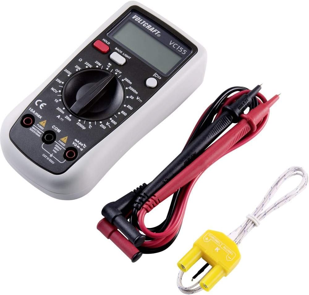
Figure 4.1: Voltcraft VC155 Multimeter showing connected test leads and the K-type temperature sensor.
- Collega sempre il nero puntale di prova per il COM presa di ingresso.
- Per volumetage, resistance, diode, continuity, and small current (mA/µA) measurements, connect the rosso puntale di prova per il VΩmAµA presa di ingresso.
- For high current (up to 10A) measurements, connect the rosso puntale di prova per il 10A max presa di ingresso.
- Assicurarsi che i collegamenti siano saldi e sicuri.
4.3 Collegamento del sensore di temperatura
To measure temperature, use the provided K-type temperature sensor.
- Connect the K-type temperature sensor's plug into the VΩmAµA E COM input jacks, observing polarity (positive to VΩmAµA, negative to COM).
5. Istruzioni per l'uso
Turn the rotary switch to the desired function to power on the multimeter. Turn it to the "OFF" position to power off.
5.1 Volume CCtage Misurazione (V=)
- Set the rotary switch to the desired "V=" range (e.g., 200mV, 2V, 20V, 200V, 600V).
- Collegare il puntale rosso al VΩmAµA jack e il puntale nero al COM cricco.
- Collegare le sonde di prova in parallelo sul componente o sul circuito da misurare.
- Leggi il vol.tage valore sul display.
5.2 Volume ACtage Misurazione (V~)
- Set the rotary switch to the desired "V~" range (e.g., 200V, 600V).
- Collegare il puntale rosso al VΩmAµA jack e il puntale nero al COM cricco.
- Collegare le sonde di prova in parallelo attraverso la tensione CAtage fonte.
- Leggi il vol.tage valore sul display.
5.3 Misurazione della corrente continua (A=)
- ATTENZIONE: Never connect the meter in parallel with a voltage sorgente quando si misura la corrente. Ciò potrebbe far saltare il fusibile o danneggiare il misuratore.
- Set the rotary switch to the desired "A=" range (e.g., 200µA, 2mA, 20mA, 200mA, 10A).
- For µA/mA ranges, connect the red test lead to the VΩmAµA jack. For 10A range, connect the red test lead to the 10A max jack. Collegare il puntale di prova nero al COM cricco.
- Aprire il circuito in cui si desidera misurare la corrente e collegare il misuratore in serie.
- Leggere il valore corrente sul display.
5.4 Misurazione della resistenza (Ω)
- Set the rotary switch to the desired "Ω" range (e.g., 200Ω, 2kΩ, 20kΩ, 200kΩ, 2MΩ, 20MΩ).
- Collegare il puntale rosso al VΩmAµA jack e il puntale nero al COM cricco.
- Prima di misurare la resistenza, assicurarsi che il circuito o il componente siano disattivati.
- Collegare le sonde di prova al componente.
- Leggere il valore di resistenza sul display.
5.5 Test di continuità (•))))
- Impostare l'interruttore rotante su "•)))" posizione.
- Collegare il puntale rosso al VΩmAµA jack e il puntale nero al COM cricco.
- Assicurarsi che il circuito sia disattivato.
- Collegare le sonde di prova al circuito o al componente.
- If continuity exists (resistance below approximately 50Ω), the buzzer will sound. The display will show the resistance value.
5.6 Test diodo (→|)
- Impostare l'interruttore rotante su "→|" posizione.
- Collegare il puntale rosso al VΩmAµA jack e il puntale nero al COM cricco.
- Assicurarsi che il diodo sia scollegato dal circuito.
- Collegare la sonda rossa all'anodo e la sonda nera al catodo del diodo. Il display mostrerà la tensione direttatage goccia.
- Invertire le sonde. Il display dovrebbe visualizzare "OL" (Open Loop) per indicare un diodo funzionante.
5.7 Senza contatto voltage (NCV) Test
- Impostare l'interruttore rotante sulla posizione "NCV".
- Tenere la parte superiore del multimetro vicino a una tensione CAtage fonte (ad esempio, un filo elettrico o una presa elettrica).
- Il misuratore emetterà un segnale acustico e l'indicatore NCV si accenderà se la tensione CAtage viene rilevato.
5.8 Misurazione della temperatura (°C/°F)
- Set the rotary switch to the "°C" or "°F" position.
- Connect the K-type temperature sensor to the VΩmAµA E COM jacks.
- Posizionare la punta del sensore di temperatura sull'oggetto di cui si desidera misurare la temperatura o nelle sue vicinanze.
- Leggere il valore della temperatura sul display.
5.9 Funzione HOLD
- Premere il tasto PRESA button during a measurement to freeze the current reading on the display.
- Premere il tasto PRESA nuovamente il pulsante per annullare la lettura e tornare alla misurazione in tempo reale.
5.10 Funzione retroilluminazione e torcia
- Premere il tasto RETROILLUMINAZIONE button to activate the display backlight.
- Premere e tenere premuto il tasto RETROILLUMINAZIONE button to activate the integrated torch.
- Premere il tasto RETROILLUMINAZIONE button again to turn off the backlight or torch.
6. Manutenzione
6.1 Pulizia
- Turn off the meter and disconnect all test leads before cleaning.
- Pulisci la custodia con l'adamp panno e un detergente delicato. Non utilizzare abrasivi o solventi.
- Ensure no moisture enters the meter's casing.
6.2 Sostituzione della batteria
When the battery symbol appears on the display, the 9V battery needs to be replaced.
- Spegnere il misuratore e scollegare tutti i puntali di prova.
- Unscrew the retaining screw(s) on the battery compartment cover on the rear of the device.
- Remove the old battery and replace it with a new 9V block battery, observing correct polarity.
- Riposizionare il coperchio della batteria e fissarlo con la/le vite/i.
6.3 Sostituzione del fusibile
The current input jacks are protected by ceramic high-performance fuses. If the meter fails to measure current, the fuse may need replacement. Fuse replacement should only be performed by qualified personnel.
- Fusibili: F1: F 200mA/250V, F2: F 10A/250V (specific fuse ratings are typically printed near the fuse holder or in a more detailed service manual).
- Always replace with fuses of the exact same type and rating.
7. Risoluzione Dei Problemi
| Problema | Possibile causa | Soluzione |
|---|---|---|
| Nessun display o display poco luminoso | Batteria scarica o scarica. | Sostituire la batteria da 9V. |
| Letture errate | Selezione della funzione/intervallo errata; collegamento scadente del puntale di prova; puntali di prova danneggiati. | Verify function and range; ensure secure connections; inspect and replace damaged leads. |
| Impossibile misurare la corrente | Blown fuse in the current input circuit. | Sostituire il fusibile appropriato (vedere la Sezione 6.3). |
| "OL" (sovraccarico) visualizzato | Measurement exceeds the selected range; open circuit (for resistance/continuity). | Select a higher range; check for open circuits or proper connection. |
8. Specifiche
| Parametro | Valore |
|---|---|
| Display | 2000 conteggi |
| Categoria di misurazione | CATIII 600V |
| Volume DCtage (V=) | Ranges: 200mV, 2V, 20V, 200V, 600V; Basic Accuracy: 0.5% |
| Volume ACtage(V~) | Ranges: 200V, 600V; Basic Accuracy: 0.1V ~600V AC reading range |
| Corrente continua (A=) | Ranges: 200µA, 2mA, 20mA, 200mA, 10A |
| Resistenza (Ω) | Ranges: 200Ω, 2kΩ, 20kΩ, 200kΩ, 2MΩ, 20MΩ; 10MΩ DC resistance, 4.5MΩ AC resistance |
| Test di continuità | Audible buzzer below approx. 50Ω |
| Test diodi | SÌ |
| Volume senza contattotage (PCV) | Yes (230V/AC test) |
| Misurazione della temperatura | K-type sensor input |
| Fonte di alimentazione | 1 x 9V block battery (included) |
| Dimensioni (L x P x A) | 5.91 x 2.95 x 1.5 pollici (15.0 x 7.5 x 3.8 cm) |
| Peso | 7.1 once (200 grammi) |
9. Garanzia e supporto
Voltcraft products are manufactured to high-quality standards and are subject to strict quality controls. For information regarding warranty terms, technical support, or service, please refer to the documentation provided with your purchase or contact your local Voltcraft dealer or customer service center.
You can also visit the official Voltcraft websito per ulteriore assistenza e informazioni sui prodotti.