1. Introduzione
The Digilent PowerBRICKS are compact, breadboardable power supplies designed to provide reliable 5V dual output power for your electronic circuits. Powered conveniently via USB, these units integrate directly into your breadboard, offering a low-profile and efficient power solution. Each PowerBRICK can deliver up to 1.1W of power, making them suitable for a variety of prototyping and educational applications.
This manual provides essential information for the proper setup, operation, and maintenance of your PowerBRICKS device.
2. Impostazione
Follow these steps to set up your Digilent PowerBRICKS:
- Breadboard Integration: Carefully align the pins of the PowerBRICKS module with the power rails or desired section of your breadboard. Gently press down to ensure a secure connection. The module is designed for direct plug-in integration.
- Collegamento elettrico: Connect a standard USB cable from a 5V USB power source (e.g., computer USB port, USB wall adapter) to the USB connector on the PowerBRICKS module. This will supply input voltage al dispositivo.
- Ingresso volumetage Pin Header: The +Vin pin header can also serve as an input. If a USB power source is attached, this pin header becomes an output, providing access to the USB voltage. This feature allows for daisy-chaining multiple PowerBRICKS.
- Collegamento a margherita (facoltativo): To power multiple PowerBRICKS from a single USB source, connect the +Vin pins of the modules together. Note that the first PowerBRICK in the chain limits the input current. The entire chain should not exceed a total output power of 2.2W. For maximum individual output capabilities (current and capacitive load), each PowerBRICK should be powered individually via its USB connector or +Vin pin.
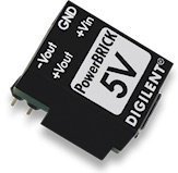
Image: The Digilent PowerBRICKS module, showing its compact design and pins for breadboard integration. This image illustrates how the module connects directly to a breadboard for power distribution.
3. Istruzioni per l'uso
Once properly set up, the PowerBRICKS module provides the following outputs:
- Positive Output (Vout): +5V at up to 250mA. The maximum capacitive load for this output is 22uF.
- Negative Output (-Vout): -5V at up to -200mA. The maximum capacitive load for this output is 47uF.
Ensure that the total power draw from a single PowerBRICK does not exceed 1.1W. When daisy-chaining, the total power output for the entire chain should not exceed 2.2W.
4. Manutenzione
The Digilent PowerBRICKS are designed for durability and require minimal maintenance. To ensure optimal performance and longevity:
- Gestione: Handle the module with care to avoid damaging the pins or internal components.
- Pulizia: If necessary, gently clean the module with a dry, soft cloth. Avoid using liquids or abrasive cleaners.
- Magazzinaggio: Store the PowerBRICKS in a dry, cool environment, away from direct sunlight and extreme temperatures.
- Condizioni ambientali: Avoid exposing the device to excessive moisture or dust.
5. Risoluzione Dei Problemi
If you encounter issues with your PowerBRICKS, consider the following troubleshooting steps:
- Nessuna potenza in uscita:
- Verify that the USB power source is active and providing 5V.
- Ensure the USB cable is securely connected to both the power source and the PowerBRICKS module.
- Check for proper insertion into the breadboard; ensure all pins make good contact.
- Volume erratotage Uscita:
- Confirm that the load connected to the PowerBRICKS does not exceed the specified current limits (+250mA for +5V, -200mA for -5V).
- Ensure the total power draw (1.1W per module, 2.2W for a daisy-chain) is not exceeded. Overloading can cause voltage gocce.
- Check for any short circuits in your breadboard setup.
- Surriscaldamento: If the module feels excessively hot, immediately disconnect the power. This usually indicates an overload or a short circuit in the connected circuit. Review your circuit design and power consumption.
6. Specifiche
| Caratteristica | Specificazione |
|---|---|
| Numero di modello | 410-294-A |
| Ingresso volumetage | 5V via USB or +Vin pin |
| Volume di uscitatage (Vout) | +5V @ 250mA |
| Volume di uscitatage (-Vout) | -5V @ -200mA |
| Max Capacitive Load (Vout) | 22 uF |
| Max Capacitive Load (-Vout) | 47 uF |
| Max Power Output (Single) | 1.1W |
| Max Power Output (Daisy-Chain) | 2.2W |
| Dimensioni del prodotto | 1.18 x 1.18 x 0.39 pollici |
| Peso dell'articolo | 0.32 once |
| Codice UPC | 717520027638 |
7. Informazioni sulla garanzia
For detailed warranty information regarding your Digilent PowerBRICKS, please refer to the official Digilent website or the documentation provided at the time of purchase. Warranty terms and conditions may vary.
8. Supporto
If you require further assistance or have questions not covered in this manual, please visit the official Digilent support page or contact their customer service. You can find more resources and contact information on the Digilent websito.


