1. Introduzione
This manual provides detailed instructions for the safe and effective operation of your BENNING CM 12 True RMS Digital Power Clamp Multimeter. Please read this manual thoroughly before using the device and keep it for future reference. The BENNING CM 12 is designed for demanding measurement tasks in industrial and commercial environments, offering precise measurements of AC, AC+DC True RMS, inrush current, and more, with data logging and Bluetooth connectivity.
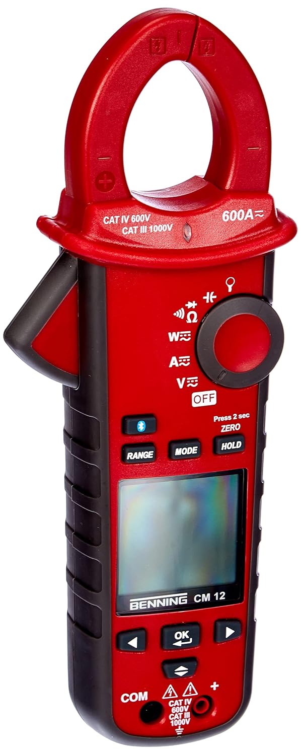
Figura 1: The Benning CM 12 True RMS Digital Power Clamp Multimeter. This image displays the main unit with its red casing, clamp jaw, display screen, and control buttons.
2. Informazioni sulla sicurezza
Per evitare lesioni personali e danni allo strumento, osservare sempre le seguenti precauzioni di sicurezza:
- Non utilizzare il misuratore se appare danneggiato o se l'isolamento dei puntali di prova è compromesso.
- Prima di effettuare le misurazioni, assicurarsi di aver selezionato la funzione e l'intervallo corretti.
- Non superare i limiti massimi di input per nessuna funzione.
- Prestare attenzione quando si lavora con voltagsuperiori a 30 V CA RMS, 42 V di picco o 60 V CC, poiché rappresentano un rischio di scossa elettrica.
- Scollegare sempre l'alimentazione dal circuito e scaricare tutti i componenti ad alto volumetagcondensatori prima di eseguire test di resistenza, continuità, diodi o capacità.
- Rispettare i codici di sicurezza locali e nazionali.
3. Componenti del prodotto
The BENNING CM 12 package includes the following items:
- BENNING CM 12 Potenza Digitale Clamp Multimetro
- Cavi di prova (rosso e nero)
- Batterie AAA (6 incluse)
- Custodia per il trasporto
- Manuale dell'utente (questo documento)
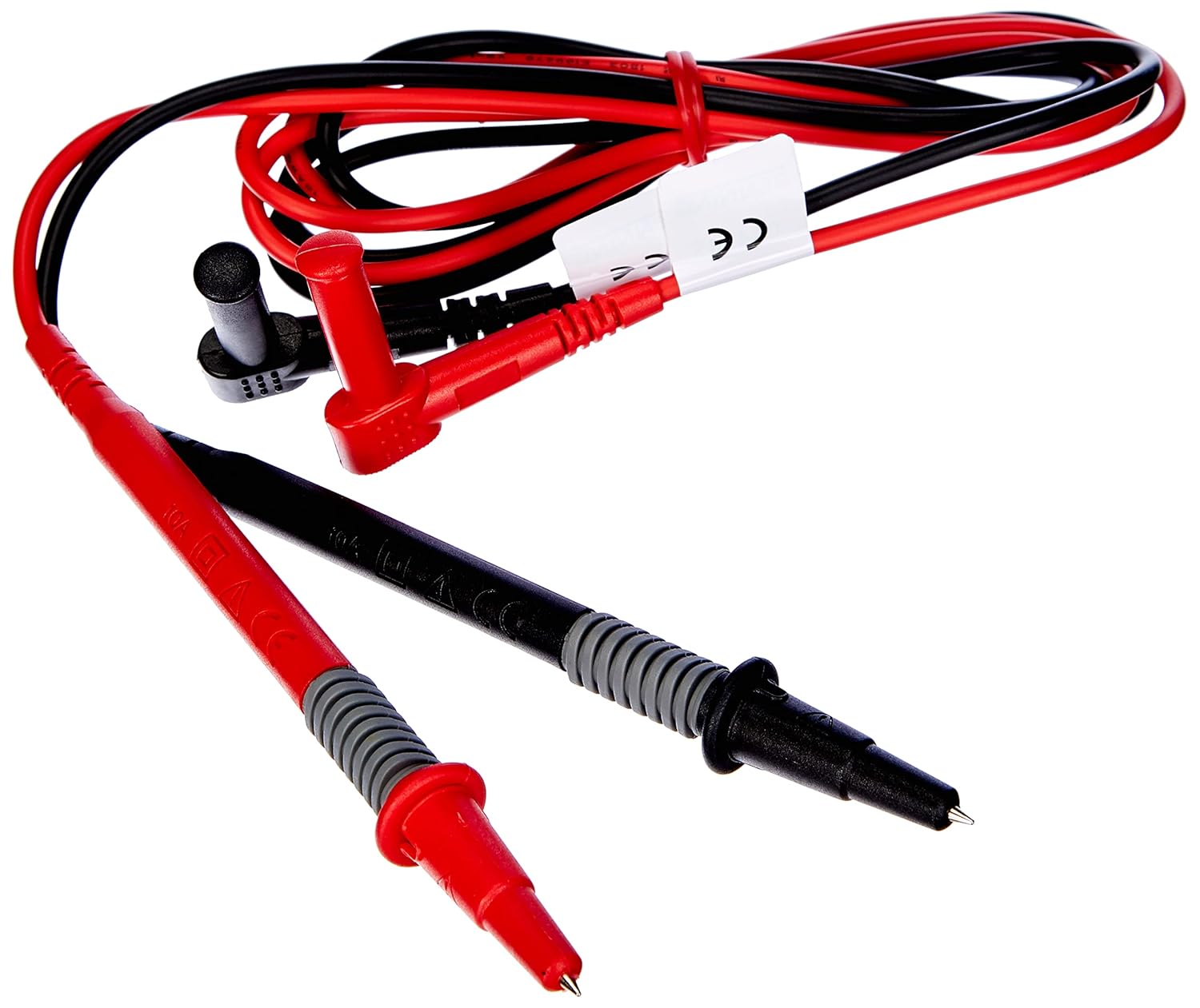
Figura 2: Red and black test leads. These leads are used for voltage, resistance, continuity, and other measurements.

Figura 3: Six AAA batteries. These batteries power the Benning CM 12 multimeter.

Figura 4: Black carrying case. This case provides protection and portability for the multimeter and its accessories.
4. Impostazione
4.1. Installazione della batteria
- Individuare il coperchio del vano batteria sul retro del dispositivo.
- Utilizzare un cacciavite per aprire il vano batteria.
- Insert six (6) AAA batteries, ensuring correct polarity as indicated inside the compartment.
- Riposizionare il coperchio del vano batteria e fissarlo con la vite.
4.2. Accensione iniziale
Turn the rotary switch to any measurement function (e.g., V~ for AC Voltage) to power on the device. The display will illuminate, indicating the device is ready for use.
5. Istruzioni per l'uso
The BENNING CM 12 offers a variety of measurement functions. Select the desired function using the rotary switch.
5.1. Misurazione della corrente CA/CC (Clamp Funzione)
- Ruotare il selettore rotativo in posizione 'A~' (corrente CA) o 'A=' (corrente CC).
- Premere il tasto clamp grilletto per aprire la mascella.
- Racchiudere un singolo conduttore con il clamp mascella. Assicurarsi che la mascella sia completamente chiusa.
- Leggere il valore corrente sul display.
- For AC+DC True RMS measurements, ensure the appropriate mode is selected if available via the MODE button.
5.2. Volumetage Misurazione (AC/DC)
- Inserire il puntale di prova rosso nel jack di ingresso 'VΩ' e il puntale di prova nero nel jack di ingresso 'COM'.
- Turn the rotary switch to 'V~' (AC Voltage) o 'V=' (Volume DCtagE).
- Collegare i puntali di prova in parallelo al circuito o al componente in prova.
- Leggi il vol.tage valore sul display.
5.3. Resistance and Continuity Measurement
- Prima di effettuare la misurazione, assicurarsi che il circuito sia disattivato.
- Insert test leads as for voltage misurazione.
- Turn the rotary switch to 'Ω' (Resistance/Continuity).
- Collegare i puntali di prova al componente.
- For continuity, the meter will beep if resistance is below approximately 30Ω - 100Ω.
5.4. Prova del diodo
- Assicurarsi che il circuito sia disattivato.
- Insert test leads as for voltage misurazione.
- Turn the rotary switch to the 'Diode' symbol.
- Collegare il cavo rosso all'anodo e il cavo nero al catodo del diodo. Una tensione direttatage drop (approx. 0.8V) will be displayed. Reverse the leads for an open circuit reading.
5.5. Misurazione della corrente di spunto
This function measures the initial surge of current when a device (e.g., motor, lamp) is first turned on.
- Turn the rotary switch to the 'A~' position.
- Press the 'INRUSH' button (if dedicated) or activate via 'MODE' button.
- Clamp the meter around the power conductor of the device.
- Turn on the device to measure the inrush current.
5.6. Power Measurement (W) and Power Factor
The BENNING CM 12 can simultaneously detect current (A) and voltage (V) to calculate active power (W) and power factor in AC/DC networks.
- Turn the rotary switch to the 'W' (Power) position.
- Connect the test leads for voltage measurement and clamp the jaw around the current conductor.
- The display will show active power (W) and power factor.
5.7. Data Logger Function (LOG) and Bluetooth Interface
The device features a data logger capable of storing 10,000 readings with a sampling rate from 1 second to 10 minutes. It also includes a Bluetooth interface for data connection to smartphones or tablets via the "BENNING MM-CM Link" app.
- Download and install the "BENNING MM-CM Link" app from your device's app store (iOS and Android compatible).
- Activate Bluetooth on your smartphone/tablet and on the BENNING CM 12 (refer to the device's specific button for Bluetooth activation, usually a dedicated button or a long press of 'MODE').
- Pair the device with the app.
- Use the app to configure logging parameters (sampling rate, start/stop logging) and to view/export recorded data.
5.8. Low-Pass Filter (HFR)
The HFR (High-Frequency Rejection) low-pass filter is used for accurate measurements on clocked motor drives or other noisy environments by filtering out high-frequency interference.
- Activate the HFR filter via a dedicated button or by pressing the 'MODE' button in relevant measurement functions (e.g., AC Voltage or Current).
- The display will typically show an indicator when the filter is active.
5.9. Total Harmonic Distortion (THD) Measurement
The THD function assesses network quality by measuring the total harmonic distortion of voltage or current waveforms.
- Select the THD function using the rotary switch or 'MODE' button in AC Voltage/Current modes.
- Connect the meter as appropriate for voltage o misurazione corrente.
- The display will show the THD value.
5.10. Two-Pole Rotary Field Testing
This function is used to determine the phase sequence in three-phase systems.
- Turn the rotary switch to the 'Rotary Field' symbol (if dedicated) or select via 'MODE' button in a relevant AC voltage funzione.
- Connect the test leads to two phases of the three-phase system.
- The display will indicate the phase sequence (e.g., L1-L2, L2-L3).
6. Manutenzione
6.1. Pulizia
Pulisci la custodia con l'adamp panno e detergente delicato. Non utilizzare abrasivi o solventi. Assicurarsi che il dispositivo sia spento e scollegato da qualsiasi circuito prima di pulirlo.
6.2. Sostituzione della batteria
Quando sul display compare l'indicatore di batteria scarica, sostituire le batterie come descritto nella Sezione 4.1. Rimuovere le batterie se il dispositivo non verrà utilizzato per un periodo prolungato per evitare perdite.
6.3. Conservazione
Store the multimeter in its carrying case in a cool, dry environment, away from direct sunlight and extreme temperatures. Remove batteries for long-term storage.
7. Risoluzione Dei Problemi
| Problema | Possibile causa | Soluzione |
|---|---|---|
| Il misuratore non si accende. | Batterie scariche o installate in modo errato. | Controllare la polarità delle batterie; sostituire le batterie. |
| Nessuna lettura o "OL" (sovraccarico) visualizzato. | Incorrect range selected, open circuit, or measurement exceeds range. | Select appropriate range, check circuit connections, ensure measurement is within device limits. |
| Letture imprecise. | Collegamento scadente del puntale di prova, interferenza esterna o batteria scarica. | Ensure secure connections, move away from strong electromagnetic fields, replace batteries. |
| Problemi di connessione Bluetooth. | Bluetooth not activated on device/phone, app issues, or out of range. | Ensure Bluetooth is on for both devices, restart app, move closer to the meter. |
8. Specifiche
| Caratteristica | Dettaglio |
|---|---|
| Numero di modello | CM12 |
| Tipo di misurazione | True RMS (AC, AC+DC) |
| Corrente di spunto | SÌ |
| Carica Profile Registrazione | Yes (single-phase and three-phase) |
| Misura di potenza | Active Power (W), Power Factor |
| Test di continuità | 30 Ω - 100 Ω |
| Test diodi | 0.8 Volt |
| Rotary Field Testing | Bipolare |
| Filtro passa basso | HFR (High-Frequency Rejection) |
| Harmonic Measurement | THD (distorsione armonica totale) |
| Registratore dati | 10,000 readings, 1s - 10min samptasso di ling |
| Interfaccia | Bluetooth (iOS and Android app "BENNING MM-CM Link") |
| Fonte di alimentazione | 6 batterie AAA (incluse) |
| Dimensioni del prodotto | 11.42 x 5.12 x 2.76 pollici |
| Peso dell'articolo | 1.3 libbre (590 grammi) |
| Produttore | Essere |

Figura 5: Dimensionale view of the Benning CM 12 Multimeter, indicating its approximate height of 11 inches (27 cm).
9. Informazioni sulla garanzia
BENNING products are manufactured to high-quality standards. For specific warranty terms and conditions, please refer to the warranty card included with your product or visit the official BENNING websito. Conservare la prova d'acquisto per eventuali reclami in garanzia.
10. Assistenza clienti
If you encounter any issues or have questions regarding your BENNING CM 12, please contact BENNING customer support. You can find contact information on the official BENNING websito o tramite il tuo distributore locale.
- Websito: www.benning.de (Si prega di verificare la propria regione) websito)
- E-mail: Fare riferimento al websito per indirizzi email di contatto specifici.
- Telefono: Fare riferimento al websito per numeri di contatto specifici.