1. Introduzione
This manual provides detailed instructions for the installation, operation, and maintenance of the BFT Phobos BT A40 automatic double swing gate operator. Please read this manual thoroughly before installation and use to ensure proper function and safety.

Figura 1: Oltreview of the BFT Phobos BT A40 Kit Components.
2. Informazioni sulla sicurezza
Per evitare lesioni o danni all'apparecchiatura, osservare sempre le seguenti precauzioni di sicurezza:
- L'installazione deve essere eseguita da personale qualificato nel rispetto delle normative locali.
- Scollegare l'alimentazione prima di eseguire qualsiasi intervento di manutenzione o installazione.
- Tenere bambini e animali domestici lontani dall'area del cancello durante il funzionamento.
- Non azionare il cancello se una qualsiasi parte è danneggiata o non funziona correttamente.
- Assicurarsi che tutti i dispositivi di sicurezza (fotocellule, arresto di emergenza) siano installati correttamente e funzionino.
- In case of power failure, use the provided emergency release keys to manually open the gate.
3. Componenti inclusi
The BFT Phobos BT A40 kit typically includes the following components:
- 2 x BFT PHOBOS BT A40 electromechanical actuators with fixings.
- 1 x BFT THALIA LIGHT control panel with integrated radio receiver (memory for 63 manual transmitters).
- 1 x Control panel housing (hermetic).
- 3 x BFT MITTO B4 4-channel remote controls.
- 1 x BFT Radius LED BT A R1 flashing lamp con antenna.
- 1 x Pair of BFT Compacta A20-180 pivoting photocells (transmitter and receiver).
- 4 x Keys for emergency gate opening in case of power failure.
- Mounting brackets for posts and gate leaves.
- Various small parts and accessories for installation (e.g., nuts, bolts, seals).

Figure 2: Small Parts and Accessories.
4. Configurazione e installazione
This section outlines the general steps for installing the BFT Phobos BT A40 system. Professional installation is highly recommended.
4.1 Installazione dell'attuatore
Install the two BFT PHOBOS BT A40 electromechanical actuators on each gate leaf. Ensure the mounting brackets are securely fastened to both the gate post and the gate leaf. The maximum distance between the edge of the post and the hinge axis should be up to 8 cm.

Figure 3: BFT PHOBOS BT A40 Actuators and THALIA LIGHT Control Unit.
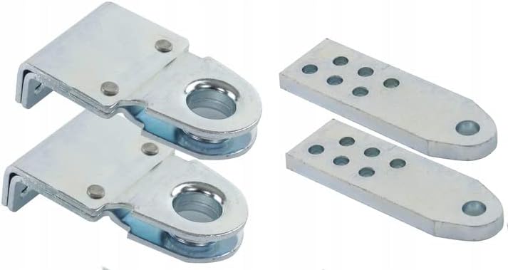
Figure 4: Mounting Brackets.
The magnetic limit switch system ensures maximum operating precision and very easy and quick adjustment. The integrated adjustable limit switch means there is no need to use bumpers screwed to the ground.
4.2 Installazione del pannello di controllo
Mount the BFT THALIA LIGHT control panel in its hermetic housing in a protected location, typically near the gate. Connect the actuators, power supply, and all safety devices to the control panel according to the wiring diagram provided in the full installation manual (not included in this summary).
4.3 Installazione della fotocellula
Install the BFT Compacta A20-180 pivoting photocells on opposite sides of the gate opening, ensuring they are aligned. These photocells provide a safety barrier, preventing the gate from closing if an obstruction is detected.

Figure 5: BFT Compacta A20-180 Pivoting Photocell Pair.
4.4 Flashing Lamp Installazione
Mount the BFT Radius LED BT A R1 flashing lamp in a visible location. This lamp provides a visual warning when the gate is in motion.

Figure 6: BFT Radius LED BT A R1 Flashing Lamp.
5. Istruzioni per l'uso
The BFT Phobos BT A40 system is designed for automatic operation of double swing gates.
5.1 Funzionamento del telecomando
Use the BFT MITTO B4 4-channel remote controls to operate the gate. Each button can be programmed for different functions (e.g., open/close both leaves, open/close single leaf, pedestrian access). Refer to the control panel manual for remote control programming instructions.

Figure 7: BFT MITTO B4 Remote Controls.
5.2 Funzionamento automatico
Once activated, the gate will open or close automatically. The D-TRACK technology ensures complete application safety by optimally selecting the necessary forces at each point of the automation's operation. The system will detect obstructions via the photocells and reverse or stop to prevent damage or injury.
5.3 Sblocco manuale di emergenza
In the event of a power failure, use the provided emergency keys to manually unlock and open the gate. Insert the key into the actuator's release mechanism and turn it as indicated in the actuator's specific manual.
6. Manutenzione
Regular maintenance ensures the longevity and reliable operation of your BFT gate operator.
- Mensile: Check the gate's movement for any unusual noises or resistance. Ensure the photocells are clean and unobstructed. Test the safety features.
- Trimestrale: Inspect all mounting points and fasteners for tightness. Check the condition of the actuator's screw nut; the modernized design (deeper screw nut) reduces the possibility of accidental contamination of the mechanism, but regular inspection is still advised.
- Annualmente: Far ispezionare il sistema da un tecnico qualificato.
- Mantenere l'area attorno al cancello libera da detriti e vegetazione.
7. Risoluzione Dei Problemi
Questa sezione affronta i problemi più comuni che potresti incontrare. Per problemi più complessi, contatta un tecnico qualificato.
| Problema | Possibile causa | Soluzione |
|---|---|---|
| Il cancello non risponde al telecomando. | Batteria del telecomando scarica, telecomando fuori portata, interruzione di corrente, telecomando non programmato. | Replace battery, move closer to gate, check power supply, reprogram remote. |
| Il cancello si ferma o inverte il movimento durante la chiusura. | Obstruction detected by photocells, D-TRACK system detecting unusual resistance. | Clear obstruction from photocell path, clean photocells, check gate for physical obstructions or binding. |
| lampeggianteamp non funziona. | Lamp bulb faulty, wiring issue. | Check connections, replace lamp se necessario. |
| Il cancello funziona lentamente o con difficoltà. | Basso volumetage, mechanical friction, actuator issue. | Check power supply, lubricate gate hinges, contact technician. |
8. Specifiche
Key technical specifications for the BFT Phobos BT A40 system:
- Modello: Phobos BT A40
- Produttore: BFT
- Tipo di attuatore: 24V Electromechanical irreversible drive
- Lunghezza massima dell'anta del cancello: Up to 4 meters (13.1 ft) per leaf
- Peso massimo dell'anta del cancello: Up to 250 kg (551 lbs) per leaf
- Dimensioni del prodotto (L x P x A): 26 x 18 x 14 cm (10.2 x 7.1 x 5.5 pollici)
- Peso del prodotto: 2.21 kg (4.87 libbre)
- Colore: Argento
- Numero di riferimento: OGBBFTADB0037
- Numero modello articolo: 2611950

Figure 8: Actuator Dimensions (Phobos BT A40 relevant).
9. Garanzia e supporto
Information regarding product warranty and availability of spare parts is not explicitly provided in this manual. Please refer to your purchase documentation or contact your BFT dealer for details on warranty coverage and spare parts availability.


