1. Introduzione
This manual provides essential instructions for the safe and effective operation of your AOPUTTRIVER AP-770D Digital Multimeter. Please read this manual thoroughly before use and retain it for future reference. This device is designed for accurate measurement of various electrical parameters in a wide range of applications.
Informazioni sulla sicurezza
- Rispettare sempre i codici di sicurezza locali e nazionali.
- Non utilizzare il misuratore se appare danneggiato o se l'isolamento dei puntali di prova è compromesso.
- Prima di effettuare le misurazioni, assicurarsi di aver selezionato la funzione e l'intervallo corretti.
- Avoid making measurements on circuits with voltages exceeding the meter's rated limits.
- Sostituire le batterie e i fusibili solo con quelli del tipo e della potenza specificati.
2. Contenuto della confezione
Verifica che tutti gli articoli elencati di seguito siano presenti nel tuo pacco:
- AOPUTTRIVER AP-770D Digital Multimeter
- Cavi di prova (rosso e nero)
- Termocoppia di tipo K (sonda di temperatura)
- Batteria da 9 V
- Manuale d'uso
- Borsa da trasporto
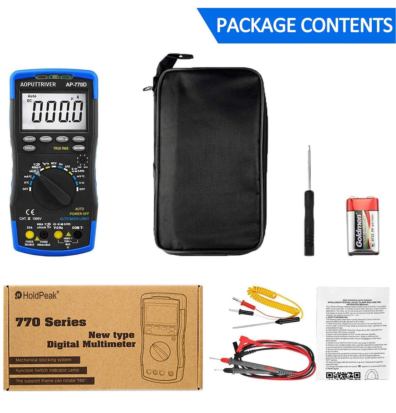
Figure 2.1: Contents of the AP-770D package, including the multimeter, test leads, temperature probe, battery, manual, and carrying pouch.
3. Prodotto finitoview
Familiarize yourself with the components of your AP-770D Digital Multimeter:

Figura 3.1: Fronte view of the AP-770D with key functions labeled.
- Luce rossa NCV: Indicates non-contact voltage rilevamento.
- Sensore CDS: Sensore di luce per retroilluminazione automatica.
- Luce verde NCV: Indicates non-contact voltage rilevamento.
- Area di rilevamento NCV: Point for non-contact voltage rilevamento.
- Display: Large LCD for reading measurements.
- Tasto SELECT: Toggles between functions within a rotary switch position.
- Tasto HOLD: Blocca la lettura corrente del display.
- Chiave RANGE: Switches between auto-ranging and manual ranging.
- REL ▲ Key: Attiva la modalità di misurazione relativa.
- Tasto Hz/Duty: Seleziona la misurazione della frequenza o del ciclo di lavoro.
- Tasto MAX/MIN: Registra le letture massime e minime.
- Jack di ingresso per test hFE del transistor: Per testare il guadagno del transistor.
- Interruttore rotante: Seleziona la funzione di misurazione desiderata.
- Ingresso VΩHz: Terminale di ingresso per voltage misure di resistenza, frequenza, capacità, diodi e continuità.
- Ingresso COM: Terminale comune (negativo) per tutte le misurazioni.
- Presa di ingresso 20A: Input terminal for high AC/DC current measurements (up to 20A).
- µA mA T+ Input: Input terminal for microampere/milliampmisurazioni di corrente e temperatura.

Figure 3.2: Dimensions of the AP-770D and its 180° swivel stand.
4. Impostazione
4.1 Installazione della batteria
The AP-770D requires one 9V battery for operation. To install or replace the battery:
- Assicurarsi che il multimetro sia spento e che i puntali di prova siano scollegati.
- Individuare il coperchio del vano batterie sul retro dell'unità.
- Utilizzare un cacciavite per allentare la vite che fissa il coperchio della batteria.
- Remove the cover and insert the 9V battery, observing correct polarity.
- Riposizionare il coperchio della batteria e serrare la vite.
4.2 Accensione iniziale
Turn the rotary switch from the 'OFF' position to any desired measurement function. The display will illuminate. The meter features an auto backlight that activates in low-light conditions.
5. Modalità operative
The AP-770D offers a variety of measurement functions. Always ensure the correct function is selected and test leads are connected to the appropriate input jacks.
5.1 volumitage Misurazione (AC/DC)
Per misurare il volumetage:
- Set the rotary switch to the 'V~' (AC Voltage) or 'V∓' (DC Voltage) posizione.
- Connect the red test lead to the 'VΩHz' input jack and the black test lead to the 'COM' input jack.
- Collegare le sonde di prova al circuito o al componente da misurare.
- Leggi il vol.tage valore sul display.
5.2 Misurazione della corrente (AC/DC)
Per misurare la corrente:
- Set the rotary switch to the appropriate current range (µA, mA, or A). Use the 'SELECT' button to toggle between AC and DC current if applicable.
- Connect the red test lead to the 'µA mA T+' or '20A' input jack (depending on expected current) and the black test lead to the 'COM' input jack.
- Collegare le sonde di prova in serie al circuito da misurare.
- Leggere il valore corrente sul display.
5.3 Misurazione della resistenza
Per misurare la resistenza:
- Set the rotary switch to the 'Ω' (Resistance) position.
- Connect the red test lead to the 'VΩHz' input jack and the black test lead to the 'COM' input jack.
- Connect the test probes across the component to be measured. Ensure the circuit is de-energized.
- Leggere il valore di resistenza sul display.
5.4 Misurazione della capacità
Per misurare la capacità:
- Set the rotary switch to the '––||––' (Capacitance) position.
- Connect the red test lead to the 'VΩHz' input jack and the black test lead to the 'COM' input jack.
- Collegare le sonde di prova al condensatore. Assicurarsi che il condensatore sia scarico prima di effettuare il test.
- Leggere il valore della capacità sul display.
5.5 Misurazione della frequenza e del ciclo di lavoro
Per misurare la frequenza o il ciclo di lavoro:
- Impostare il selettore rotativo sulla posizione 'Hz'.
- Connect the red test lead to the 'VΩHz' input jack and the black test lead to the 'COM' input jack.
- Collegare le sonde di prova alla sorgente del segnale.
- Press the 'Hz/Duty' button to toggle between frequency and duty cycle readings.
5.6 Test diodi
Per eseguire un test dei diodi:
- Set the rotary switch to the '→|–' (Diode) position.
- Connect the red test lead to the 'VΩHz' input jack and the black test lead to the 'COM' input jack.
- Collegare la sonda rossa all'anodo e la sonda nera al catodo del diodo.
- Un volume in avantitage drop will be displayed for a good diode. Reverse the probes; the display should show 'OL' (Open Loop).
5.7 Prova di continuità
Per eseguire un test di continuità:
- Set the rotary switch to the '▪))' (Continuity) position.
- Connect the red test lead to the 'VΩHz' input jack and the black test lead to the 'COM' input jack.
- Collegare le sonde di prova al circuito o al componente.
- Se esiste continuità (resistenza al di sotto di una certa soglia), il cicalino suonerà.
5.8 Misurazione della temperatura
Per misurare la temperatura:
- Set the rotary switch to the '°C/°F' (Temperature) position.
- Connect the K-type thermocouple to the 'µA mA T+' and 'COM' input jacks, observing polarity.
- Posizionare la punta della termocoppia sull'oggetto di cui si desidera misurare la temperatura o al suo interno.
- Read the temperature value on the display. Use the 'SELECT' button to switch between Celsius and Fahrenheit.

Figure 5.1: Measuring temperature of a liquid using the AP-770D's temperature probe.
5.9 Senza contatto voltage (NCV) Rilevamento
Per rilevare il volume CAtage senza contatto:
- Impostare l'interruttore rotante sulla posizione 'NCV'.
- Move the NCV detection area (top of the meter) close to the conductor being tested.
- The NCV red and green lights will flash, and the buzzer will sound, indicating the presence of AC voltage. The intensity of the indication increases with stronger voltage.

Figure 5.2: Using the NCV function to detect live wires without direct contact.
5.10 hFE Test (Transistor Gain)
To test transistor hFE:
- Impostare il selettore rotante sulla posizione 'hFE'.
- Insert the transistor leads (Emitter, Base, Collector) into the corresponding holes in the 'Transistor hFE Test Input Jack'.
- Leggere il valore hFE sul display.
6. Specifiche
| Caratteristica | Valore |
|---|---|
| Conteggio display | 40,000 Conteggi |
| Vero RMS | SÌ |
| Auto Range | SÌ |
| VNC | SÌ |
| Volume AC/DCtage | Fino a 1000V |
| Corrente AC / DC | Fino a 20A |
| Resistenza | Fino a 60 MΩ |
| Capacità | Fino a 60 mF |
| Frequenza | Fino a 10 MHz |
| Temperatura | Sì (con termocoppia di tipo K) |
| Test diodi | SÌ |
| Test di continuità | Sì (con cicalino) |
| Prova hFE | SÌ |
| Retroilluminazione automatica | SÌ |
| Spegnimento automatico | SÌ |
| Standard di sicurezza | IEC-1010, CAT III 1000V |
| Fonte di alimentazione | Batteria da 9 V |
| Dimensioni | 20 cm x 9 cm x 4 cm (circa) |
| Peso | 350 grammi |
7. Manutenzione
7.1 Pulizia
Pulisci il contatore casing con annuncioamp panno e detergente delicato. Non utilizzare abrasivi o solventi. Assicurarsi che il misuratore sia completamente asciutto prima dell'uso.
7.2 Sostituzione della batteria
Quando sul display compare il simbolo della batteria, sostituire la batteria da 9 V come descritto nella Sezione 4.1.
7.3 Sostituzione del fusibile
If the current measurement function fails, the fuse may need replacement. Refer to the full user manual for detailed instructions on fuse replacement. Always use fuses with the specified ratings (e.g., Fused 20A MAX, Fused 500mA MAX).

Figure 7.1: The mechanical blocking system helps prevent incorrect lead insertion, enhancing safety during use.
8. Risoluzione Dei Problemi
- Nessuna visualizzazione: Controllare l'installazione della batteria e il livello di carica. Sostituire la batteria se necessario.
- 'OL' sullo schermo: Indica una condizione di fuori scala o un circuito aperto. Selezionare una gamma più alta o controllare i collegamenti.
- Letture errate: Ensure correct function and range are selected. Verify test lead connections and integrity.
- Errore nella misurazione della corrente: Controllare il fusibile. Sostituirlo se bruciato (vedere Sezione 7.3).
9. Garanzia e supporto
For warranty information or technical support, please refer to the contact details provided in your product packaging or visit the AOPUTTRIVER official website. Do not attempt to repair the device yourself, as this may void the warranty and pose a safety risk.


