1. Informazioni sulla sicurezza
Please read and understand all safety information and operating instructions before using this multimeter. Failure to follow these instructions may result in electric shock, fire, or damage to the meter.
- Prima di effettuare qualsiasi misurazione, assicurarsi sempre che i puntali di prova siano collegati correttamente e che l'interruttore di funzione sia impostato sulla gamma corretta.
- Non tentare di misurare il voltages or currents exceeding the maximum rated values for this meter.
- Prestare la massima attenzione quando si lavora con circuiti sotto tensione. Alta vol.tagpossono essere pericolosi.
- Never open the meter casing unless specifically instructed for battery or fuse replacement. Ensure test leads are disconnected before opening.
- Per garantire letture accurate, sostituire la batteria quando compare l'indicatore di batteria scarica.
- Non utilizzare il misuratore se appare danneggiato o se l'isolamento dei puntali di prova è compromesso.
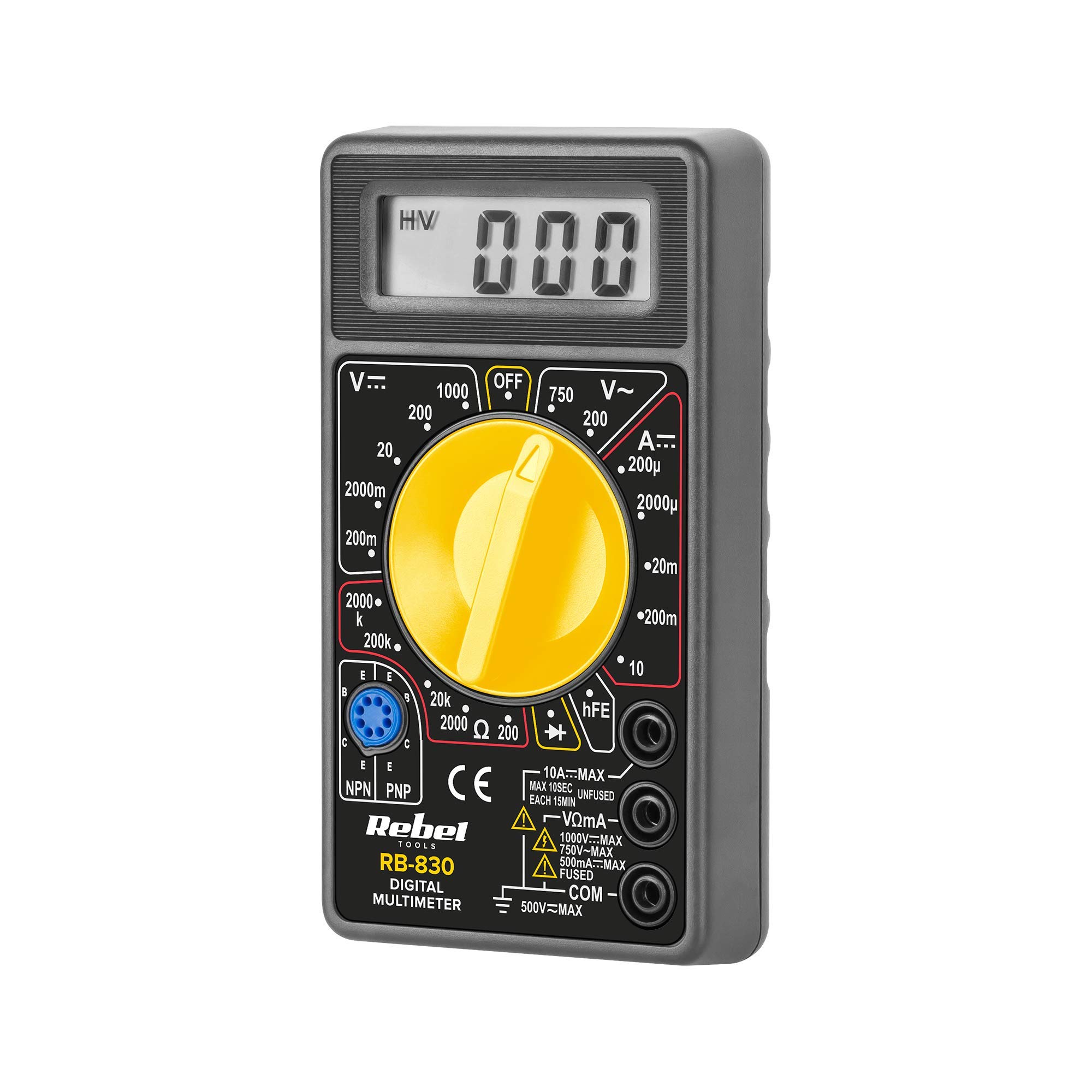
Figura 1: Posteriore view of the Rebel MIE-RB-830 Multimeter, showing the battery compartment cover and a warning label. The label advises removing test leads before opening the case to avoid electrical shock and to install fuses with correct amp/volt ratings. It also indicates the power supply is a 9V battery, type NEDA 1604 9V 6F22.
2. Prodotto finitoview
The Rebel MIE-RB-830 is a compact, battery-operated digital multimeter designed for measuring DC/AC voltage, DC current, resistance, diode, and transistor (hFE) values. It is suitable for general electrical testing and troubleshooting.
2.1. componenti
- Unità multimetro digitale
- Cavi di prova (rosso e nero)
- Batteria da 9 V (può essere inclusa o venduta separatamente)
- Manuale dell'utente (questo documento)

Figura 2: The Rebel MIE-RB-830 Digital Multimeter shown with its accompanying red and black test leads. The multimeter features a large LCD display and a rotary function switch.

Figura 3: Avvicinamento view of the red and black test leads. These leads are essential for connecting the multimeter to the circuit under test.
3. Impostazione
3.1. Installazione della batteria
- Assicurarsi che il multimetro sia spento e che tutti i puntali di prova siano scollegati.
- Individuare il coperchio del vano batteria sul retro del misuratore (fare riferimento alla Figura 1).
- Svitare la/le vite/e di fissaggio e rimuovere con cautela il coperchio.
- Insert a new 9V battery (NEDA 1604 or 6F22 type), observing the correct polarity (+ and -).
- Richiudere il coperchio del vano batteria e fissarlo con la/le vite/i.
3.2. Collegamento dei puntali di prova
- Collegare il rosso test lead to the "VΩmA" input jack.
- Collegare il nero test lead to the "COM" (common) input jack.
- For current measurements exceeding 200mA (up to 10A), connect the red test lead to the "10A" input jack.
4. Istruzioni per l'uso
4.1. Selezione della funzione
Turn the rotary switch to the desired measurement function and range. Always start with a higher range if the approximate value is unknown to prevent overloading the meter.
4.2 Misurazione del volume CCtage (V–)
- Impostare il selettore rotativo sul volume CC desideratotage (V–) range (e.g., 20V, 200V).
- Collegare il puntale di prova rosso al lato positivo (+) del circuito e il puntale di prova nero al lato negativo (-).
- Leggi il vol.tage valore sul display LCD.
4.3. Misurazione del volume CAtage (V∼)
- Impostare il selettore rotativo sul volume CA desideratotage (V∼) range (e.g., 200V, 750V).
- Collegare i puntali di prova attraverso la tensione CAtage fonte.
- Leggi il vol.tage valore sul display LCD.
4.4. Measuring DC Current (A–)
Attenzione: To measure current, the meter must be connected in series with the circuit. Never connect the meter in parallel with a voltage source when in current mode, as this can damage the meter and the circuit.
- Set the rotary switch to the desired DC Current (A–) range (e.g., 20mA, 200mA, 10A).
- For currents up to 200mA, ensure the red lead is in the "VΩmA" jack. For currents up to 10A, move the red lead to the "10A" jack.
- Aprire il circuito in cui si desidera misurare la corrente e collegare il misuratore in serie.
- Leggere il valore corrente sul display LCD.
4.5. Misurazione della resistenza (Ω)
Attenzione: Prima di misurare la resistenza, assicurarsi che il circuito o il componente sottoposto a test sia disattivato.
- Set the rotary switch to the desired Resistance (Ω) range (e.g., 200Ω, 2kΩ, 200kΩ).
- Collegare i puntali di prova al componente o al circuito da misurare.
- Leggere il valore della resistenza sul display LCD.
4.6. Test diodo (→|–)
- Set the rotary switch to the Diode Test (→|–) position.
- Collegare il puntale di prova rosso all'anodo del diodo e il puntale di prova nero al catodo.
- Il display mostrerà il volume in avantitagcaduta di tensione (tipicamente da 0.5 V a 0.8 V per i diodi al silicio).
- Invertire i cavi. Il display dovrebbe visualizzare "OL" (Open Loop) per un diodo funzionante.
4.7. Test del transistor (hFE)
- Portare il selettore in posizione hFE.
- Identificare se il transistor è NPN o PNP.
- Insert the transistor's emitter, base, and collector leads into the corresponding sockets on the hFE test socket.
- Leggere il valore hFE (guadagno di corrente CC) sul display.
5. Manutenzione
5.1. Sostituzione della batteria
Quando sul display compare l'indicatore di batteria scarica, sostituire la batteria da 9 V come descritto nella Sezione 3.1. L'utilizzo di una batteria scarica può causare letture imprecise.
5.2. Sostituzione del fusibile
If the current measurement function stops working, the fuse may need replacement. This operation should only be performed by qualified personnel.
- Assicurarsi che il multimetro sia spento e che tutti i puntali di prova siano scollegati.
- Aprire il retro casing of the meter (this may involve more screws than just the battery compartment).
- Locate the blown fuse and replace it with a fuse of the exact same type and rating (e.g., F200mA/250V for mA range, F10A/250V for 10A range). Refer to the internal markings or specifications for precise fuse ratings.
- Rimontare con attenzione il misuratore, assicurandosi che tutte le viti siano serrate.
5.3. Pulizia
Pulisci il contatore con l'adamp panno e detergente delicato. Non utilizzare abrasivi o solventi. Mantenere il misuratore asciutto.
6. Risoluzione Dei Problemi
| Problema | Possibile causa | Soluzione |
|---|---|---|
| Nessun display o display debole | Batteria scarica o scarica | Sostituire la batteria da 9V. |
| Letture errate | Low battery; Incorrect range selection; Poor test lead connection | Replace battery; Select appropriate range; Ensure leads are firmly connected. |
| Misurazione della corrente non funzionante | Blown fuse; Incorrect lead connection for current | Replace fuse (see Section 5.2); Ensure red lead is in "VΩmA" or "10A" jack as appropriate. |
| "OL" (sovraccarico) visualizzato | Measured value exceeds selected range; Open circuit (for resistance/continuity) | Selezionare una gamma più alta; controllare che il circuito non presenti interruzioni. |
7. Specifiche
| Funzione di misurazione | Allineare | Precisione |
|---|---|---|
| Volume DCtage (V–) | 200 mV, 2 V, 20 V, 200 V, 1000 V | ±(0.5% + 2 cifre) |
| Volume ACtage (V∼) | 200V, 750V | ±(1.2% + 10 cifre) |
| DC Current (A–) | 200µA, 2mA, 20mA, 200mA, 10A | ±(1.0% + 2 cifre) |
| Resistenza (Ω) | 200Ω, 2kΩ, 20kΩ, 200kΩ, 2MΩ | ±(0.8% + 2 cifre) |
| Test diodi | SÌ | Volume in avantitage goccia |
| Test del transistor (hFE) | SÌ | hFE value |
| Alimentazione elettrica | Batteria da 9 V (NEDA 1604 o 6F22) | |
| Display | 3½ Digit LCD, Max. 1999 | |
| Dimensioni | Circa. 13.5 x 10 x 4 cm | |
| Peso | Approx. 107 grams (without battery) | |
| Temperatura di esercizio | da 0°C a 40°C (da 32°F a 104°F) | |
| Temperatura di conservazione | da -10°C a 50°C (da 14°F a 122°F) | |
| Standard di sicurezza | CE, RoHS |
8. Garanzia e supporto
This Rebel MIE-RB-830 Digital Multimeter is covered by a standard manufacturer's warranty against defects in materials and workmanship. Please refer to the warranty card included with your purchase or contact your retailer for specific warranty terms and conditions.
For technical support or service inquiries, please contact the point of purchase or visit the official Rebel websito per le informazioni di contatto.