1. Introduzione
This manual provides essential information for the installation, operation, and maintenance of your HALLOMOTOR M620 G510 Mid Drive Motor Conversion Kit. This kit is designed to convert a standard bicycle into an electric bicycle, offering enhanced power and performance. Please read this manual thoroughly before installation and use to ensure safe and optimal operation of your e-bike system.
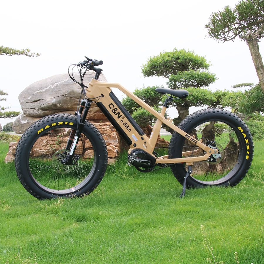
Immagine 1: Es.ample of a bicycle converted with the HALLOMOTOR M620 G510 Mid Drive Motor Kit.
2. Informazioni sulla sicurezza
Always prioritize safety when working with or operating your e-bike conversion kit. Failure to follow safety instructions can result in serious injury or damage to the product.
- Leggi tutte le istruzioni: Familiarize yourself with all components and procedures before beginning installation or operation.
- Installazione professionale consigliata: In caso di dubbi su qualche passaggio, rivolgersi a un meccanico di biciclette qualificato.
- Indossare dispositivi di protezione: Quando si guida la propria e-bike, indossare sempre il casco e gli adeguati dispositivi di sicurezza.
- Controllare le connessioni: Ensure all electrical connections are secure and waterproof before riding, especially after rain or washing.
- Sicurezza della batteria: Use only compatible batteries. Do not short-circuit, puncture, or expose the battery to extreme temperatures.
- Ispezioni regolari: Periodically check all bolts, cables, and components for tightness and wear.
- Esposizione all'acqua: While the motor has an IP65 waterproof rating, avoid submerging the motor or exposing electrical connections to high-pressure water jets.
- Normative locali: Be aware of and comply with all local laws and regulations regarding e-bike use.
3. Contenuto della confezione
Carefully unpack the box and verify that all items listed below are present and undamaged. If any items are missing or damaged, contact your vendor immediately.

Image 2: All components included in the conversion kit.
- 1 x 48V/52V 1000W Mid Drive Motor (UART Protocol)
- 1 Pair x Brake Levers
- 1 paio di pedivelle
- 1 x 44T Chainwheel
- 1 set x acceleratore a pollice
- 1 set x sensore di velocità
- 1 x DPC18 Display
- 1 cavo 4 in 1
- 1 Set x Accessories (mounting hardware, lock nuts, etc.)
4. Configurazione e installazione
The installation of the M620 G510 mid-drive motor requires careful attention to detail. It is crucial that the bicycle frame's bottom bracket area is compatible and prepared correctly for the motor's dimensions.
- Prepare the Bicycle Frame: Ensure the frame adapter and bicycle frame are properly aligned. For optimal fit and concentricity, the frame's bottom bracket area may require heat treatment after welding to match the motor's installation dimensions and mounting hole locations.
- Montare il motore: Align the three mounting holes on the motor with the corresponding holes on the bicycle frame's bottom bracket. Carefully fit the motor into position.
- Fissare il motore: Use the provided accessories and mounting hardware to firmly secure the motor to the frame. Ensure all bolts are tightened to the manufacturer's specifications.
- Install Crank Arms and Chainwheel: Attach the crank arms and the 44T chainwheel to the motor's shaft.
- Install Brake Levers and Thumb Throttle: Mount the brake levers and thumb throttle onto the handlebars.
- Install DPC18 Display: Secure the DPC18 display to the handlebars in a position that is easily visible and accessible.
- Collegare il cablaggio: Use the 4-in-1 cable to connect the display, throttle, brake levers, and speed sensor to the motor. Ensure all connections are snug and correctly oriented (refer to wiring diagram if available).
- Installare il sensore di velocità: Mount the speed sensor on the chainstay and align the magnet on a spoke of the rear wheel.
- Collegare la batteria: Connect your compatible 48V or 52V battery to the motor system. Ensure the battery is securely mounted on the bicycle.
- Controllo iniziale: Before riding, perform a thorough check of all installed components, connections, and ensure the brakes and gears function correctly.

Image 3: Mid-drive motor installed on a bicycle.
5. Istruzioni per l'uso
The DPC18 display serves as the Human Machine Interface (HMI) for your HALLOMOTOR M620 G510 system, providing essential information and control over the motor's functions.

Image 4: DPC18 Display and motor connections.
5.1 DPC18 Display Overview
The DPC18 display features a high-contrast LCD screen designed for clear readability, even in direct sunlight. Its compact design offers protection against water and dust (IP65 rated).
- Accensione/spegnimento: Tenere premuto il pulsante di accensione sul display per accendere o spegnere il sistema.
- Selezione del livello di assistenza: Use the up/down buttons to cycle through different levels of pedal assist (e.g., 0-5 or 0-9, depending on configuration).
- Visualizzazione delle informazioni: The screen shows real-time data such as current speed, battery level, assist level, trip distance, odometer, and more.
- Assistenza alla camminata: Some displays offer a walk assist function, typically activated by holding the down button, which provides low-speed motor assistance for pushing the bike.
- Menu Impostazioni: Access the settings menu (refer to the DPC18 specific manual for detailed navigation) to customize parameters like wheel size, speed limit, and unit preferences.
5.2 Utilizzo dell'acceleratore a pollice
The thumb throttle provides on-demand power without pedaling. Apply gentle pressure to the throttle to engage the motor. Always use the throttle responsibly and be aware of your surroundings.
5.3 Brake Levers with Cut-off Sensor
The included brake levers are equipped with motor cut-off sensors. Engaging either brake lever will immediately cut power to the motor, enhancing safety during braking.
6. Manutenzione
Regular maintenance ensures the longevity and reliable performance of your HALLOMOTOR M620 G510 conversion kit.
- Pulizia: Mantenere puliti il motore, il display e i collegamenti elettrici. Utilizzare un adamp panno per pulire le superfici. Evitare il lavaggio ad alta pressione direttamente sui componenti elettrici.
- Ispezione dei cavi: Periodically check all cables and connectors for signs of wear, fraying, or damage. Ensure they are securely plugged in.
- Controllo del dispositivo di fissaggio: Regularly inspect all mounting bolts and fasteners on the motor, display, and other components. Tighten any loose fasteners to prevent vibration damage.
- Catena e trasmissione: Mantieni la catena e la trasmissione della tua bicicletta (corona, cassetta, deragliatore) come faresti con una bicicletta normale. Mantieni la catena pulita e lubrificata.
- Cura della batteria: Follow the battery manufacturer's instructions for charging, storage, and maintenance. Avoid fully discharging the battery and store it in a cool, dry place.
- Rumore del motore: If you notice unusual noises from the motor, discontinue use and inspect for any issues.
7. Risoluzione Dei Problemi
Questa sezione fornisce soluzioni ai problemi più comuni che potresti riscontrare. Per problemi più complessi, contatta l'assistenza tecnica.
| Problema | Possibile causa | Soluzione |
|---|---|---|
| Motor does not turn on/no power to display. | Battery not connected, low battery, loose power cable, faulty display. | Check battery connection and charge level. Ensure all power cables are securely connected. Test display if possible. |
| Motor provides no assist when pedaling. | Assist level set to 0, speed sensor misalignment/damage, brake lever engaged, loose motor cable. | Increase assist level on display. Check speed sensor alignment and connection. Ensure brake levers are fully released. Inspect motor cable connections. |
| Inaccurate speed reading on display. | Speed sensor misalignment, magnet missing, incorrect wheel size setting. | Adjust speed sensor and magnet position. Verify wheel size setting in DPC18 display menu. |
| Il motore fa un rumore insolito. | Loose mounting bolts, internal motor issue, foreign object. | Check and tighten motor mounting bolts. Discontinue use and contact support if noise persists. |
8. Specifiche
Key technical specifications for the HALLOMOTOR M620 G510 Mid Drive Motor Conversion Kit.

Image 5: Technical specifications and dimensions of the motor.
| Caratteristica | Dettaglio |
|---|---|
| Tipo di motore | Mid Drive Motor (M620 G510) |
| Volume nominaletage | 48V / 52V CC |
| Potenza nominale | 1000W |
| Coppia massima | 160 Nm |
| Costruzione | Trasmissione ad ingranaggi |
| Efficienza | ≥ 80% |
| Grado di rumore | < 55 dB |
| Grado di impermeabilità | Grado di protezione IP65 |
| Display | DPC18 (UART Protocol) |
| Standard dell'albero | ISIS |
| Peso netto del motore | 5.3 kg |
| Temperatura di esercizio | -20°C a 80°C |
| Certificati | Certificazione CE/EN14764/ROHS |
9. Garanzia e supporto
HALLOMOTOR products are typically covered by a manufacturer's warranty against defects in materials and workmanship. The specific terms and duration of the warranty may vary. Please retain your proof of purchase for warranty claims.
9.1 Richieste di garanzia
In the event of a warranty claim, please contact your original point of purchase or HALLOMOTOR customer support with your product details and proof of purchase. Do not attempt to repair the motor or components yourself, as this may void the warranty.
9.2 Supporto tecnico
For technical assistance, troubleshooting beyond this manual, or inquiries about parts, please contact HALLOMOTOR customer service. Provide your product model number and a detailed description of the issue to receive efficient support.
Contact information for HALLOMOTOR support can typically be found on their official websito o tramite il tuo rivenditore.


