1. Introduzione
This manual provides detailed instructions for the proper installation, operation, and maintenance of the GODIYMODULES High Voltage DC Converter Module Board. This module is designed to provide stable high voltage DC and filament voltage, suitable for applications such as powering Nixie tubes and Magic Eye tubes.

Immagine 1.1: Dall'alto verso il basso view of the GODIYMODULES High Voltage DC Converter Module Board. This image shows the overall layout of the components, including capacitors, inductors, the DC input jack, and the terminal blocks for input and output connections.
2. Informazioni sulla sicurezza
WARNING: This module generates high voltage. Improper handling can result in electric shock, injury, or damage to equipment. Always exercise extreme caution when working with high voltage circuiti.
- Prima di effettuare qualsiasi collegamento o regolazione, assicurarsi che l'alimentazione sia scollegata.
- Do not touch any components on the board when power is applied.
- Use appropriate insulation and safety equipment.
- Verificare che tutti i collegamenti siano corretti prima di applicare l'alimentazione.
- This module is intended for experienced electronics hobbyists and professionals.
3 Caratteristiche
- Designed for Nixie and Magic Eye Tube anode and filament power supply.
- Alto volume regolabiletage DC output.
- Dedicated 6.3V filament voltage uscita.
- Compact board design.
4. Specifiche
| Parametro | Valore |
|---|---|
| Ingresso volumetage | CC 9V-12V |
| DC Socket Specification | 5.5*2.1 mm (Inner Positive, Outer Negative) |
| Alto volumetage Uscita | DC 150V-280V / 15mA (Adjustable) |
| Filamento Vol.tage Uscita | DC 6.3V / 1500mA |
| Dimensioni | Circa 5.24 x 3.82 x 1.34 pollici (confezione) |
| Peso | Circa 0.634 once |
| Materiale | Metallo, Plastica |
5. Configurazione e connessioni
Follow these steps to correctly connect the High Voltage DC Converter Module Board to your system. Ensure all power is disconnected before proceeding.
5.1 Collegamento dell'alimentazione in ingresso
The module accepts a DC input voltage between 9V and 12V. There are two methods for providing input power:
- Presa di alimentazione CC: Use a DC power adapter with a 5.5*2.1 mm plug. The plug must be inner positive and outer negative.
- Morsettiera: Connect your DC 9V-12V power supply to the designated input terminals on the green screw terminal block. Observe correct polarity.
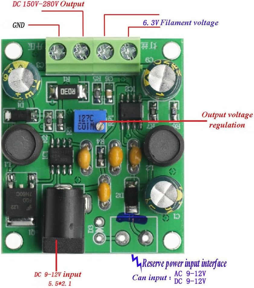
Image 5.1: Connection diagram showing input and output terminals. The DC 9-12V input can be connected via the barrel jack (5.5*2.1mm, inner positive, outer negative) or the screw terminal block. The image also indicates the output voltage regulation potentiometer.

Image 5.2: Detailed connection diagram illustrating the input power options (DC 9-12V via barrel jack or screw terminals) and the output connections for 6.3V filament voltage, GND, and adjustable DC 150-280V. The output voltage adjustment potentiometer is also clearly marked.
5.2 Collegamenti di uscita
The module provides two main outputs via the green screw terminal block:
- DC 150V-280V Output: Questo è il volume altotage output, adjustable via the onboard potentiometer. Connect the anode of your Nixie or Magic Eye tube to this output.
- Uscita CC 6.3V: This output provides 6.3V for tube filaments. Connect the filament of your tube to this output.
- TERRA: Common ground connection for both outputs.
Prima di applicare l'alimentazione, assicurarsi che tutti i collegamenti siano saldi e correttamente polarizzati.
6. Istruzioni per l'uso
6.1 Accensione
Once all connections are verified and secure, connect the DC 9V-12V power supply to the module. The module will immediately begin generating the output voltages.
6.2 Adjusting High Voltage Uscita
L'alto volumetage output (DC 150V-280V) is adjustable using the blue potentiometer located on the board. Use a small screwdriver to carefully turn the potentiometer:
- Girando in senso orario Volere aumento il volume di uscitatage.
- Girando Antiorario Volere diminuire il volume di uscitatage.
Always use a multimeter to measure the output voltage while adjusting to prevent over-voltage damage to your connected components.

Immagine 6.1: In alto view of the module, clearly showing the blue potentiometer used for adjusting the high voltage uscita.
7. Manutenzione
The GODIYMODULES High Voltage DC Converter Module Board is designed for reliable operation and requires minimal maintenance.
- Mantenere il modulo pulito e libero da polvere e detriti.
- Ensure adequate ventilation around the module to prevent overheating.
- Evitare di esporre il modulo all'umidità o a temperature estreme.
- Controllare regolarmente i collegamenti per verificare che non siano allentati o corrosi.
8. Risoluzione Dei Problemi
- Nessuna uscita Voltage:
- Verify the input power supply is connected and providing 9V-12V DC.
- Check the polarity of the input DC power plug (inner positive, outer negative).
- Ensure all output connections are secure.
- Volume di uscita erratotage:
- Per alto voltage output, adjust the potentiometer as described in Section 6.2.
- Use a multimeter to accurately measure the output voltages.
- Assicurare il volume di inputtage è stabile e rientra nell'intervallo specificato.
- Surriscaldamento del modulo:
- Assicurare un adeguato flusso d'aria attorno al modulo.
- Verify that the load connected to the outputs does not exceed the specified current limits (15mA for HV, 1500mA for 6.3V).
9. Supporto
For further assistance or technical inquiries, please refer to the seller's contact information on the product purchase page or visit the GODIYMODULES official support channels.


