1. Introduzione
This manual provides detailed instructions for the safe and effective use of your KAIWEETS HT118A Digital Multimeter and KET20 Silicone Multimeter Test Leads. The HT118A is a True RMS 6000-count digital multimeter designed for accurate measurement of various electrical parameters. The KET20 test leads are engineered for high safety and durability, complementing the multimeter's capabilities. Please read this manual thoroughly before operation to ensure proper usage and to prevent potential hazards.
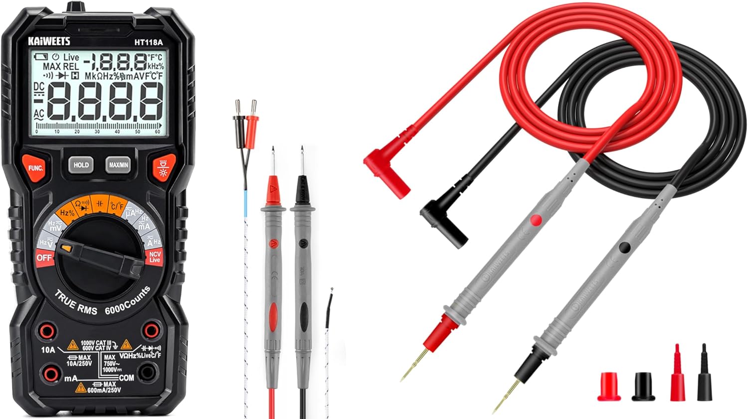
Figure 1: KAIWEETS HT118A Digital Multimeter and KET20 Test Leads. This image displays the HT118A multimeter on the left, featuring its large display and rotary dial, alongside the KET20 silicone test leads on the right, coiled and ready for use.
2. Informazioni sulla sicurezza
Rispettare sempre le precauzioni di sicurezza quando si utilizzano apparecchiature di prova elettriche. La mancata osservanza di queste precauzioni può causare scosse elettriche, lesioni o danni al misuratore o all'apparecchiatura sottoposta a prova.
- Ensure the multimeter and test leads are in good condition before each use. Inspect for any damage to the casing, insulation, or connectors.
- The KET20 test leads are rated for CAT III 1000V and CAT IV 600V. Always use appropriate safety category leads for the measurement task.
- Non applicare voltage or current that exceeds the maximum ratings specified for the multimeter.
- Scollegare sempre l'alimentazione dal circuito prima di collegare o scollegare i puntali di prova, soprattutto quando si misura la corrente o la resistenza.
- Prestare attenzione quando si lavora con voltagsuperiori a 30 V CA RMS, 42 V di picco o 60 V CC, poiché rappresentano un rischio di scossa elettrica.
- Non utilizzare il misuratore in ambienti con presenza di gas, vapori o polveri esplosivi.
- Per garantire letture accurate, sostituire tempestivamente le batterie quando compare l'indicatore di batteria scarica.
- Refer to the specifications section for detailed safety ratings and measurement limits.
3. Prodotto finitoview
3.1 KAIWEETS HT118A Digital Multimeter
The HT118A is a versatile digital multimeter featuring True RMS measurement for accurate readings on non-sinusoidal waveforms. It offers a 6000-count resolution on its large 2.9-inch backlit LCD, ensuring clear visibility of measurements.
- Capacità di misurazione: Misura DC/AC voltage up to 1000V/750V, DC/AC current up to 10A, resistance up to 60 MOhms, capacitance, frequency, duty cycle, temperature, diodes, and continuity.
- Gamma automatica: Semplifica il funzionamento selezionando automaticamente l'intervallo di misurazione corretto.
- LED Lightning Jacks: Flashing LED lights guide the user to the correct input jacks for the selected function.
- Volume senza contattotage (NCV) Rilevamento: Per identificare i cavi sotto tensione senza contatto diretto.
- Rilevamento di cavi sotto tensione: Specific function to detect live electrical lines.
- Data Hold and MAX/MIN: Functions to freeze readings and record maximum/minimum values.

Figure 2: LED Lightning Jacks. This image highlights the LED indicators around the input jacks of the HT118A multimeter, which illuminate to guide the user to the correct probe connection for the selected function.

Figure 3: 2.9" HTN Backlit Screen and Auto-ranging. This image shows the multimeter's large, orange-backlit display with dual readings, illustrating its auto-ranging capability for accurate AC/DC measurements.

Figure 4: HT118A Multimeter Functions and Battery Compartment. This image provides an overview of the various measurement functions available on the HT118A, including AC/DC voltage, current, frequency, resistance, temperature, capacitance, diodes, continuity, data retention, non-contact voltage, and live line detection. It also shows the battery compartment and kickstand.

Figure 5: Temperature Measurement. This image demonstrates the HT118A multimeter measuring temperature using the included K-Type thermocouple, shown immersed in a glass of water.
3.2 Cavi di prova in silicone per multimetro KAIWEETS KET20
The KET20 test leads are designed for enhanced safety and performance, featuring durable silicone insulation and gold-plated probes.
- Valutazioni di sicurezza: CAT III 1000V and CAT IV 600V, 20A current rating, suitable for professional electrical testing.
- Materiale: Temperature-resistant soft silicone material ensures flexibility and prevents hardening in various environments. Non-toxic and eco-friendly.
- Sonde: Ultra-sharp 2mm gold-plated probes for precise contact on high-density circuit boards.
- Costruzione del filo: 47 strands of 0.12mm copper wire for excellent tensile strength, flexibility, low resistance, and reliable electrical conductivity.
- Connettori: Universal 4mm banana plugs, compatible with most digital multimeters and clamp metri.
- Lunghezza: 48 inches (120cm) long for extended reach.

Figure 6: KET20 Test Leads Safety and Features. This image illustrates the key features of the KET20 test leads, including their 0.7mm tip, silicone material, 4mm banana plug, and 120cm length, along with their CAT IV 600V and CAT III 1000V safety ratings.

Figure 7: KET20 Test Leads Higher Safety and Durability. This image emphasizes the robust construction of the KET20 test leads, highlighting their durability, high-temperature resistance, safety, convenience, and universal compatibility.

Figure 8: KET20 Test Leads Silicone Material Properties. This image visually demonstrates the heat and cold resistance of the silicone material used in the KET20 test leads, showing them exposed to flame and ice, indicating suitability for extreme environments.

Figure 9: KET20 Test Leads Probe Details. This image provides a close-up view of the test lead probes, highlighting their flexible silicone construction, high-purity copper wire, and gold-plated tips.
4. Impostazione
4.1 Installazione della batteria
- Assicurarsi che il multimetro sia spento.
- Locate the battery compartment cover on the back of the multimeter (refer to Figure 4).
- Svitare la/le vite/i di fissaggio e rimuovere il coperchio.
- Inserire le batterie necessarie, rispettando la polarità corretta (+ e -).
- Richiudere il coperchio del vano batteria e fissarlo con la/le vite/i.
4.2 Collegamento dei puntali di prova
- Per la maggior parte delle misurazioni (voltage, resistance, continuity, diode, capacitance, frequency, temperature), insert the red test lead into the "VΩHz" jack and the black test lead into the "COM" jack.
- For current measurements (mA/µA), insert the red test lead into the "mAµA" jack and the black test lead into the "COM" jack.
- For high current measurements (10A), insert the red test lead into the "10A" jack and the black test lead into the "COM" jack.
- The LED lightning jacks will illuminate to indicate the correct connection points for the selected function.
5. Istruzioni per l'uso
The HT118A features auto-ranging for most functions, simplifying operation. Turn the rotary dial to the desired measurement function.
5.1 Misurazione Voltage (CA/CC)
- Ruotare la manopola sulla V~ (Vol. ACtage) o V- (DC voltage) posizione.
- Collegare il puntale di prova rosso al jack "VΩHz" e il puntale di prova nero al jack "COM".
- Collegare le sonde di prova in parallelo sul componente o sul circuito da misurare.
- Leggi il vol.tage valore sul display.
5.2 Misurazione della corrente (AC/DC)
- AVVERTIMENTO: Always disconnect power to the circuit before connecting the multimeter for current measurement.
- Ruotare la manopola sulla A~ (Corrente CA) o A- Posizione (corrente CC).
- For mA/µA measurements, connect the red test lead to the "mAµA" jack and the black test lead to the "COM" jack.
- For 10A measurements, connect the red test lead to the "10A" jack and the black test lead to the "COM" jack.
- Collegare le sonde di prova in serie al circuito da misurare.
- Alimentare il circuito e leggere il valore corrente sul display.
5.3 Misurazione della resistenza
- AVVERTIMENTO: Prima di misurare la resistenza, assicurarsi che il circuito sia disattivato e che tutti i condensatori siano scarichi.
- Ruotare la manopola sulla Ω Posizione (di resistenza).
- Collegare il puntale di prova rosso al jack "VΩHz" e il puntale di prova nero al jack "COM".
- Collegare le sonde di prova al componente da misurare.
- Leggere il valore di resistenza sul display.
5.4 Prova di continuità
- AVVERTIMENTO: Prima di eseguire un test di continuità, assicurarsi che il circuito sia disattivato.
- Ruotare la manopola sulla ))) Posizione (di continuità).
- Collegare il puntale di prova rosso al jack "VΩHz" e il puntale di prova nero al jack "COM".
- Touch the test probes to the two points of the circuit to be tested.
- Se esiste continuità (bassa resistenza), il misuratore emetterà un segnale acustico.
5.5 Test diodi
- AVVERTIMENTO: Prima di eseguire un test dei diodi, assicurarsi che il circuito sia disattivato.
- Ruotare la manopola sulla ->| Posizione (diodo).
- Collegare il puntale di prova rosso al jack "VΩHz" e il puntale di prova nero al jack "COM".
- Collegare la sonda rossa all'anodo e la sonda nera al catodo del diodo. Il display mostrerà la tensione direttatage goccia.
- Invertire le sonde. Il display dovrebbe visualizzare "OL" (Open Loop) per indicare un diodo funzionante.
5.6 Misurazione della capacità
- AVVERTIMENTO: Prima di effettuare la misurazione, assicurarsi che il condensatore sia completamente scarico per evitare danni al misuratore.
- Ruotare la manopola sulla -||- Posizione (Capacità).
- Collegare il puntale di prova rosso al jack "VΩHz" e il puntale di prova nero al jack "COM".
- Collegare le sonde di prova ai terminali del condensatore.
- Leggere il valore della capacità sul display.
5.7 Misurazione della frequenza e del ciclo di lavoro
- Ruotare la manopola sulla Hz% Posizione (Frequenza/Ciclo di lavoro).
- Collegare il puntale di prova rosso al jack "VΩHz" e il puntale di prova nero al jack "COM".
- Collegare le sonde di prova alla sorgente del segnale.
- Press the "FUNC" button to toggle between frequency (Hz) and duty cycle (%).
5.8 Misurazione della temperatura
- Ruotare la manopola sulla ° C / ° F Posizione (temperatura).
- Connect the K-Type thermocouple (included) to the appropriate input jacks (usually marked for temperature).
- Posizionare la sonda termocoppia nel punto in cui si desidera misurare la temperatura.
- Read the temperature value on the display. Press "FUNC" to switch between Celsius and Fahrenheit.
5.9 Senza contatto voltage (NCV) e rilevamento di cavi sotto tensione
- Ruotare la manopola sulla NCV in diretta posizione.
- Bring the top of the multimeter near the conductor to be tested.
- For NCV, the meter will beep and the NCV indicator will light up if AC voltage viene rilevato.
- For Live wire detection, press the "FUNC" button to switch to Live mode. Place the red probe into the live wire socket. The meter will indicate if it's a live wire.
5.10 Funzioni speciali
- TENERE: Premere il pulsante "HOLD" per bloccare la lettura corrente sul display. Premere nuovamente per rilasciare.
- MASSIMO/MIN: Press the "MAX/MIN" button to enter MAX/MIN recording mode. The meter will display the maximum or minimum value recorded since activation. Press again to cycle through MAX, MIN, and current readings.
- Retroilluminazione: Premere il pulsante della retroilluminazione (spesso indicato dall'icona di una lampadina) per accendere o spegnere la retroilluminazione del display.
6. Manutenzione
6.1 Pulizia
- Pulisci il contatore casing con annuncioamp panno e detersivo delicato. Non utilizzare abrasivi o solventi.
- Keep the test leads clean and free from dirt or grease to ensure good electrical contact.
6.2 Sostituzione della batteria
Quando sul display compare l'indicatore di batteria scarica, sostituire le batterie come descritto nella Sezione 4.1. Rimuovere le batterie se il misuratore non viene utilizzato per un periodo prolungato per evitare perdite.
6.3 Ispezione del cavo di prova
Regularly inspect the KET20 test leads for any signs of damage, such as cuts, cracks, or exposed wiring. Damaged leads must be replaced immediately to ensure safety and accurate measurements.
7. Risoluzione Dei Problemi
- Il contatore non si accende: Controllare l'installazione delle batterie e assicurarsi che non siano scariche.
- "OL" visualizzato: This typically means "Over Limit" or "Open Loop." The measured value is outside the meter's range, or there is an open circuit (e.g., when measuring resistance on an open wire).
- Letture imprecise:
- Controllare il livello della batteria.
- Assicurarsi che i puntali di prova siano collegati correttamente ai jack corretti.
- Verify the rotary dial is set to the appropriate function.
- Clean test probes and connection points.
- Nessun segnale acustico di continuità: Ensure the circuit is de-energized and the probes are making good contact.
8. Specifiche
| Caratteristica | Specificazione |
|---|---|
| Marca | KAIWEET - dolciumi |
| Modello | HT118A |
| Display | 6000 conteggi, LCD retroilluminato HTN da 2.9" |
| Tipo di misurazione | Vero RMS |
| Volume DCtage Gamma | Fino a 1000V |
| Volume ACtage Gamma | Fino a 750V |
| Gamma di corrente CC/CA | Fino a 10A |
| Intervallo di resistenza | Fino a 60 MOhm |
| Capacità | SÌ |
| Frequenza / ciclo di lavoro | SÌ |
| Misurazione della temperatura | Yes, with K-Type Thermocouple |
| Test diodi | SÌ |
| Test di continuità | SÌ |
| NCV/Live Detection | SÌ |
| Valutazione di sicurezza (cavi di prova) | CAT III 1000V, CAT IV 600V (20A) |
| Materiale del cavo di prova | Silicone |
| Test Lead Probe Type | Placcato oro ultra fine da 2 mm |
| Fonte di alimentazione | Alimentato a batteria |
| Colore | Nero |
Nota: le specifiche sono soggette a modifiche senza preavviso.
9. Garanzia e supporto
I prodotti KAIWEETS sono progettati per garantire affidabilità e prestazioni. Per informazioni sulla garanzia, supporto tecnico o richieste di assistenza, consultare il sito ufficiale KAIWEETS. webo contattare il servizio clienti. Conservare la ricevuta d'acquisto come prova d'acquisto per eventuali reclami in garanzia.
Negozio ufficiale KAIWEETS: Negozio KAIWEETS su Amazon


