1. Prodotto finitoview
The ZK-SMC04 is a versatile DC 10-30V 6.6A Stepper Motor Driver Controller Integrated Board designed for precise control of 42, 57, and 86 series stepper motors. This integrated unit combines driving and control functionalities, offering forward/reverse operation, pulse speed adjustment, and angle control. It supports PLC serial communication for advanced applications.
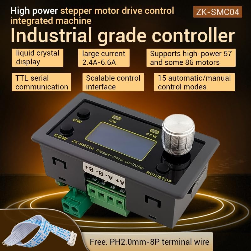
Figure 1.1: ZK-SMC04 Stepper Motor Controller highlighting features such as liquid crystal display, large current capability (2.4A-6.6A), support for high-power 57 and 86 motors, TTL serial communication, scalable control interface, and 15 automatic/manual control modes.
Le caratteristiche principali includono:
- Ampia gamma di alimentazione: DC 10-30V universal.
- High Driving Capability: Peak 6.6A.
- High Pulse Frequency: Up to 200KHZ.
- Compatibilità motore: Adaptable for 42, 57, and 86 stepper motors.
- Modalità di controllo: 15 automatic/manual control modes.
- Comunicazione: TTL serial port for remote communication control.
- Design compatto: Product size 79x43x41mm, recommended hole size 75x39mm for mounting.
2. Specifiche

Figure 2.1: Detailed specifications of the ZK-SMC04 Stepper Motor Driver Controller.
| Parametro | Valore |
|---|---|
| Modello del prodotto | ZK-SMC04 |
| Nome del prodotto | Drive Control Integrated Machine |
| Volume di fornituratage | DC 10-30V (>3A recommended) |
| Corrente di uscita | 2.4A - 6.6A (Peak) |
| Adaptable Motors | 42, 57, 86 Stepper Motors |
| Frequenza degli impulsi | Up to 200KHZ |
| Selezione modalità di controllo | 15 options (customizable) |
| Ambiente operativo | -10 ~ 60 °C (non-condensing) |
| Dimensioni della conchiglia | Dimensioni: 79x43x41mm |
| Dimensioni di apertura | 75x39mm |
| Peso dell'articolo | 3.52 once |
3. Configurazione e installazione
3.1 Schema elettrico
Proper wiring is essential for the correct operation of the ZK-SMC04. Refer to the diagrams below for power, motor, and control signal connections.

Figure 3.1: Basic product wiring diagram. Connect the DC power supply to the "Power supply +" and "Power supply -" terminals. Connect the stepper motor phases to A+, A-, B+, B- terminals.

Figure 3.2: Expansion interface and serial port output. The 8-pin expansion interface provides connections for external triggers (start/stop, switch direction), limit switches, and output signals. The serial port allows for TTL communication.

Figura 3.3: Esample connection for signal, limit switches, and output. This diagram illustrates how to connect NPN normally open proximity switches for limit detection and push buttons for start/stop and direction change functions.
3.2 Driver Settings (DIP Switches)
The ZK-SMC04 features DIP switches on the board for configuring output current and microstep resolution. Ensure the power is off before adjusting these switches.

Figure 3.4: Driver settings via DIP switches. This image details how to set the output peak current, microstep resolution, chopping mode (Smooth mode SpreadCycle or Silent Mode StealthChop), and holding current (1/2 Run or iRun).
Impostazioni correnti:
| Corrente di picco in uscita | Output Average Current | SW1 | SW2 | SW3 |
|---|---|---|---|---|
| 3.3A | 2.4A | spento | spento | spento |
| 3.7A | 2.7A | on | spento | spento |
| 4.1A | 3.1A | spento | on | spento |
| 4.5A | 3.4A | on | on | spento |
| 5.0A | 3.6A | spento | spento | on |
| 5.4A | 3.8A | on | spento | on |
| 5.8A | 4.1A | spento | on | on |
| 6.6A | 4.7A | on | on | on |
Microstep Resolution Setting:
| SW4 | SW5 | Microstep Settings |
|---|---|---|
| spento | spento | 8 |
| on | spento | 16 |
| spento | on | 32 |
| on | on | 64 |
Chopping Mode (SW6):
- spento: Smooth mode SpreadCycle (Used at high speeds)
- SU: Silent Mode StealthChop (Recommended at low speed, operates silently when the motor is at low speed or stopped)
Maintain Current (SW7):
- spento: iRun (running current)
- SU: 1/2 iRun (reduces heat generation)
4. Istruzioni per l'uso
The ZK-SMC04 features an intuitive interface with a rotary encoder and buttons for easy operation and parameter adjustment.
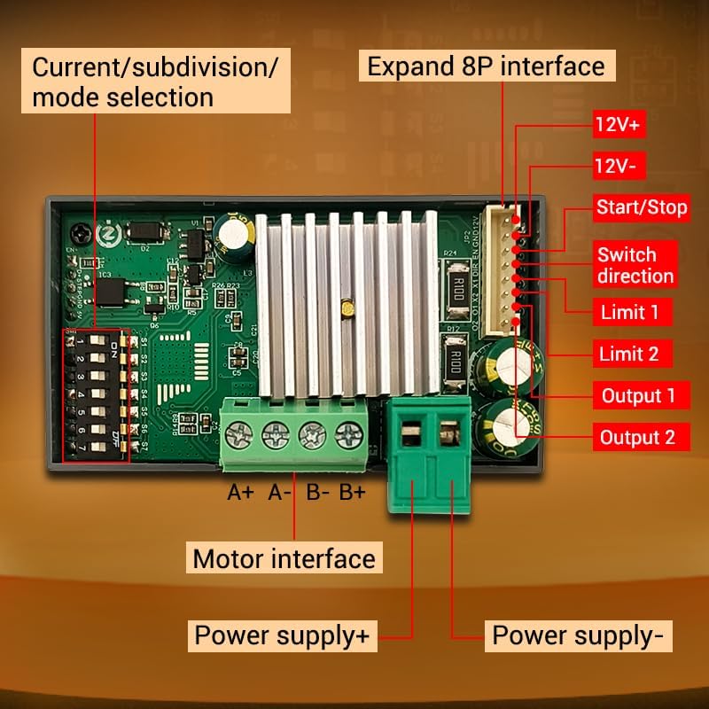
Figure 4.1: Front panel controls. The panel includes buttons for CW (Clockwise) and CCW (Counter-Clockwise) rotation, corresponding indicators, an encoder setting knob for adjustments, and a RUN/STOP button.
4.1 Funzionamento di base
- Avvio/Arresto: Premere il tasto CORRI/FERMATI button to start or stop the motor.
- Controllo della direzione:
- Premere CW pulsante per la rotazione in avanti.
- Premere Antiorario button for reverse rotation.
- Speed/Angle Adjustment: Rotate the encoder setting knob to adjust parameters such as speed or angle.
4.2 Navigazione nel menu e impostazioni dei parametri
The ZK-SMC04 allows for detailed configuration through its menu system. Follow these steps to navigate and adjust parameters:

Figure 4.2: Menu navigation and parameter adjustment. This diagram shows how to stop running and exit, enter menu settings, tune parameters, and exit parameter settings using the rotary encoder and buttons.
- Stop Running and Exit: On the running interface, adjust the speed using the rotary encoder. Press the CW button for forward rotation, CCW button for reverse. Long press the RUN/STOP button to stop running and exit.
- Accedi alle impostazioni del menu: From the running interface, long press the encoder to enter the menu settings interface.
- Naviga nel menu: In the menu settings interface, rotate the encoder to change the parameter codes from F-01 to F-14. Long press the encoder to save the parameters and exit to enter the running interface.
- Tune Parameters: In the menu settings interface, short press the encoder to enter the F-XX corresponding menu parameter setting state. The parameters will flash. Short press the shift button to rotate the encoder and adjust the parameters. Short press the RUN/STOP button to exit parameter settings and return to the main menu number adjustment interface.
4.3 Menu Functions List
The following table provides a detailed description of each menu function (F-01 to F-14) and their adjustable ranges and default values.

Figure 4.3: Comprehensive list of menu functions and their corresponding actions and settings.
| Numero | Funzione | Gamma regolabile | Valore predefinito |
|---|---|---|---|
| L'F-01 | Selection of action flow mode (Table introduction below) | 1 - 15 | 3 |
| L'F-02 | Number of positive rotation pulses/unit (High three bits by rotary encoder, low four bits by display) | 1 - 999999 | 1600 |
| L'F-03 | Forward rotation speed unit: revolutions per minute | 0.1 - 999 | 10 |
| L'F-04 | Number of reverse pulses/unit (High three bits by rotary encoder, low four bits by display) | 1 - 999999 | 1600 |
| L'F-05 | Reverse speed unit: revolutions per minute | 0.1 - 999 | 10 |
| L'F-06 | Number of cycles of work (where 0 = countless times) | 0 - 9999 or countless | 1 |
| L'F-07 | Forward time delay unit: seconds (accuracy ±0.2 seconds) | 0.0 - 999.9 | 0.0 |
| L'F-08 | Reverse time delay unit: seconds (accuracy ±0.2 seconds) | 0.0 - 999.9 | 0.0 |
| L'F-09 | Number of pulses per revolution (1-9999, x10) Unit: 10 (e.g., for 1.8° stepper motor, 8 subdivision = 160, 16 subdivision = 320, 32 subdivision = 640, 64 subdivision = 1280) | 1 - 9999 | 160 |
| L'F-10 | Main interface display content (Up: motor coil speed, Down: revolutions per minute) | 0 - 1 | 00 |
| L'F-11 | The action when pressing the pause button (0: motor slows down and stops slowly, 1: motor immediately stops) | 0 - 1 | 0 |
| L'F-12 | Acceleration and deceleration levels (1-100, 1 being the slowest and 100 being the fastest) | 1 - 100 | 20 |
| L'F-13 | Interruttore autobloccante | 0 - 1 | 0 |
| L'F-14 | Indirizzo di posta | 1 - 255 | 1 |
5. Manutenzione
To ensure the longevity and optimal performance of your ZK-SMC04 Stepper Motor Driver Controller, follow these general maintenance guidelines:
- Mantenere pulito: Regularly clean the device with a soft, dry cloth to prevent dust accumulation, especially around ventilation openings and connectors.
- Condizioni ambientali: Operate the controller within the specified temperature and humidity ranges (-10 ~ 60 °C, non-condensing) to prevent damage.
- Connessioni sicure: Controllare periodicamente tutti i collegamenti elettrici per assicurarsi che siano saldi e privi di corrosione. Collegamenti allentati possono causare un funzionamento intermittente o danni.
- Evitare il sovraccarico: Ensure the connected motor and power supply are within the specified limits of the ZK-SMC04 to prevent overheating and damage to the driver.
6. Risoluzione Dei Problemi
This section provides solutions to common issues you might encounter with the ZK-SMC04 Stepper Motor Driver Controller.

Figure 6.1: Troubleshooting guide for common operational problems.
| Fenomeno | Possibili problemi | Misure di soluzione |
|---|---|---|
| The screen doesn't light up | The motor shaft is powerless | Check the power supply circuit to see if it is connected in reverse or supplying power normally. |
| Driver chip protection | Accendere di nuovo. | |
| Il motore non gira | The pulse signal is weak | It is recommended to increase the voltage or choose a larger current. |
| The motor does not rotate and keeps vibrating | Check the motor wiring for any issues. | |
| Motor rotation error | Wrong connection of motor wire | Swap two wires of the same phase for any motor (e.g., A+ and A- exchange positions). |
| Posizione errata | Interferenza del segnale | Remove interference. |
| The motor wire has a broken circuit | Controllare e collegare correttamente. | |
| Subdivision error | Set up correct segmentation. | |
| Motor stalling vibration | The current is too small | Aumenta la corrente. |
| Turn on the mute mode, which is only suitable for low-speed states | Turn off silent mode. | |
| Short acceleration time | Extend acceleration time. | |
| Basso volumetage or low current | Appropriately increase the voltage o corrente. |
7. Garanzia e supporto
For warranty information, technical support, or any inquiries regarding the ZK-SMC04 Stepper Motor Driver Controller, please contact GODIYMODULES directly through their official channels or the retailer from whom the product was purchased.
Per i termini e le condizioni di garanzia specifici, fare riferimento alla documentazione di acquisto originale.


